Internal high-pressure forming system for pipe fittings

A technology for internal high pressure forming and pipe fittings, which is applied in the field of high pressure forming systems for pipe fittings, can solve the problems of waste of resources, increased internal high pressure source and clamping force, and bulky volume, etc., to improve work efficiency, reduce mold clamping noise, control system simple effect

Inactive Publication Date: 2015-05-20
CHINA NAT HEAVY MACHINERY RES INSTCO
View PDF7 Cites 7 Cited by
  • Summary
  • Abstract
  • Description
  • Claims
  • Application Information

AI Technical Summary

Problems solved by technology

Since the tube blank is formed under the combined action of internal high hydraulic pressure and axial force, the high pressure source must generate an internal pressure of hundreds of MPa inside the part, so there must be sufficient clamping force between the upper and lower molds to eliminate the internal high pressure during the forming process The reverse driving force on the mold ensures that the upper and lower molds are not separated, but if the mold clamping force is too large, it will cause serious deformation and wear of the mold, and the life of the mold will be greatly shortened
Therefore, the clamping force of the mold should be appropriate in the pipe forming process. If it is too large, it will cause too much damage to the mold. If it is too small, the upper and lower molds will be separated, and the quality of the pipe cannot meet the forming requirements.
[0003] In recent years, due to the integration and high-precision development of internal high pressure forming parts, the size of internal high pressure forming parts has gradually increased, and the fillet of pipe fittings has gradually decreased, which has led to a substantial increase in the internal high p

Method used


Image

  • Internal high-pressure forming system for pipe fittings
  • Internal high-pressure forming system for pipe fittings
  • Internal high-pressure forming system for pipe fittings

Examples


Embodiment Construction

[0021] The present invention will be described in detail below in conjunction with the accompanying drawings.

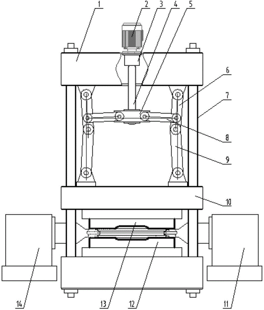
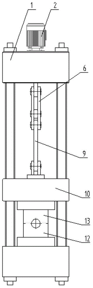
[0022] refer to figure 1 , image 3 , a high-pressure forming system for pipe fittings, including a frame 1 and a slide block 10, the slide block 10 is installed in the middle of the frame 1, and can slide up and down along the four braces 7 in the frame 1; between the frame 1 and the slide A mold clamping mechanism is arranged between the blocks 10, and the mold clamping mechanism is composed of a connecting head 5 and a group of left and right symmetrical upper links 6, small links 8, and lower links 9, all symmetrically hinged on the center line of the equipment, and the upper links The two ends of 6 are respectively hinged with the lower connecting rod 9 and the frame 1, the small connecting rod 8 is respectively hinged with the upper connecting rod 6 and the connecting head 5, and the hinge points of the small connecting rod 8 and the upper connecting rod 6 are...


PUM


Abstract

An internal high-pressure forming system for pipe fittings comprises a rack, a slider and molds. Three stages of clamping force-increasing mechanisms are arranged between the upper portion of the rack and the slider, and the first-stage force-increasing mechanism is formed by a clamping servo motor, a speed reducer and a roller screw; a connector and a group of bilaterally symmetrical upper connecting rods, small connecting rods and lower connecting rods form a secondary force-increasing mechanism and a ternary force-increasing mechanism; high-precision pressure sensors are mounted on the upper mold and form a pressure detection system with a control system; axial pipe billet feeding mechanisms disposed symmetrically are arranged between the slider and the lower portion of the rack. The clamping servo motor drives the three-stages of force-increasing mechanisms to perform clamping, clamping force is increased accurately in the forming process according to the size of increasing internal pipe forming pressure on inner cavities of the molds, the molds are kept closed constantly during forming while the molds are small in deformation under the force action, and accordingly service life of the molds is prolonged, and pipe fitting forming quality is improved; the internal high-pressure forming system is capable of controlling the clamping force in real time and has the advantages of convenience in control, simple structure and low cost.

Description

technical field [0001] The invention belongs to the technical field of internal high-pressure forming equipment for pipe fittings, and in particular relates to an internal high-pressure forming system for pipe fittings. Background technique [0002] At present, as the automotive, aviation, aerospace and machinery industries have higher and higher demands for mechanism integration and light weight, internal high pressure forming technology has been widely used, and has gradually become a method for manufacturing complex special-shaped cross-section light-body components in industrial production. An advanced forming technology. Especially in the production of automobiles, high-speed rail, and aircraft, the internal high pressure forming processing method is gradually replacing the original traditional processing method. The basic process of internal high pressure forming technology is as follows: first put the tube blank in the lower mold, then close the upper mold, seal the ...

Claims


Application Information

Patent Timeline
IPC IPC(8): B21D26/033B21D26/039
Inventor 马海宽隋健徐能惠李培力寇永乐
Owner CHINA NAT HEAVY MACHINERY RES INSTCO
Why Eureka
Try Eureka