


Quick Research
Generate reliable direction feasibility study reports for your R&D in just a few steps.

Technical Q&A
Discover and master advanced knowledge NOW. Basics, ideas, possibilities, all at once.

Find Solutions
As an expert in R&D theories, this can generate solutions to your technical problems instantly.

Evaluate Feasibility
Analyze your overall solution with one click, know your potential R&D risks in advance.

Monitor Landscape
Get weekly tech updates, stay abreast of the latest tech innovations and key insights.
Carbon fiber surface treatment method
A surface treatment and carbon fiber technology, applied in the field of carbon fiber surface treatment technology, can solve problems such as inability to continue production
- Summary
- Abstract
- Description
- Claims
- Application Information
AI Technical Summary
Problems solved by technology
Method used
Image

Examples
Embodiment 1
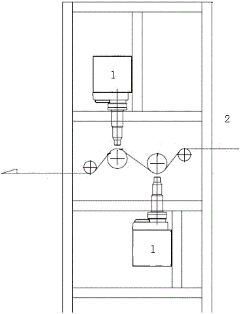
[0012] use figure 1 The low-temperature plasma device shown treats the carbon fiber surface. Under an atmospheric pressure environment, nitrogen gas is used as the carbon fiber surface treatment medium to generate low-temperature plasma, and the low-temperature plasma bombards the surface of the moving carbon fiber tow. The low-temperature plasma is a jet-type low-temperature plasma. The running speed of carbon fiber tow is 90m / h; the working environment temperature of carbon fiber treatment is 25°C; the gap between carbon fiber tow 2 and jet low-temperature plasma emission device 1 is 8mm; the environmental humidity of carbon fiber surface treatment is 60%; the power range of carbon fiber surface treatment is 1000W / bundle; low temperature plasma carbon fiber surface treatment temperature 80 ℃. The total content of polar functional groups (mainly -OH, -C=O, -COOH) on the surface of carbon fiber is 22.32%, and the interlaminar shear strength is 90MPa.
Embodiment 2
[0014] use figure 1 The low-temperature plasma device shown treats the carbon fiber surface. Under an atmospheric pressure environment, nitrogen gas is used as the carbon fiber surface treatment medium to generate low-temperature plasma, and the low-temperature plasma bombards the surface of the moving carbon fiber tow. The low-temperature plasma is a jet-type low-temperature plasma. The running speed of carbon fiber tow is 90m / h; the working environment temperature of carbon fiber treatment is 25°C; the gap between carbon fiber and plasma emission device is 8mm; the environmental humidity of carbon fiber surface treatment is 60%; the power range of carbon fiber surface treatment is 1400W / bundle; low temperature plasma The body carbon fiber surface treatment temperature is 80°C. The total content of polar functional groups (mainly -OH, -C=O, -COOH) on the surface of carbon fiber is 23.2%, and the interlaminar shear strength is 100MPa.
Embodiment 3
[0016] use figure 1 The low-temperature plasma device shown treats the carbon fiber surface. Under an atmospheric pressure environment, nitrogen gas is used as the carbon fiber surface treatment medium to generate low-temperature plasma, and the low-temperature plasma bombards the surface of the moving carbon fiber tow. The low-temperature plasma is a jet-type low-temperature plasma. The running speed of carbon fiber tow is 90m / h; the working environment temperature of carbon fiber treatment is 25°C; the gap between carbon fiber and plasma emission device is 8mm; the environmental humidity of carbon fiber surface treatment is 60%; the power range of carbon fiber surface treatment is 1600W / bundle; low temperature plasma The body carbon fiber surface treatment temperature is 80°C. The total content of polar functional groups (mainly -OH, -C=O, -COOH) on the surface of carbon fiber is 23.1%, and the interlaminar shear strength is 105MPa.
PUM
 Abstract
Description
Claims
Application Information
 - R&D Engineer
- R&D Manager
- IP Professional
- Industry Leading Data Capabilities
- Powerful AI technology
- Patent DNA Extraction
Browse by: Latest US Patents, China's latest patents, Technical Efficacy Thesaurus, Application Domain, Technology Topic, Popular Technical Reports.
© 2024 PatSnap. All rights reserved.Legal|Privacy policy|Modern Slavery Act Transparency Statement|Sitemap|About US| Contact US: help@patsnap.com