Electronic sensing type high-voltage metering device and remote testing system

An electric energy metering device and remote testing technology, applied in non-electrical signal transmission systems, measuring devices, signal transmission systems, etc., can solve problems such as large comprehensive errors, and achieve the effects of accurate measurement, excellent electrical insulation performance, and simplified system structure

Inactive Publication Date: 2015-05-20
STATE GRID HENAN ELECTRIC POWER COMPANY ZHENGZHOU POWER SUPPLY +2
View PDF7 Cites 3 Cited by
  • Summary
  • Abstract
  • Description
  • Claims
  • Application Information

AI Technical Summary

Problems solved by technology

[0005] The technical problem to be solved by the present invention is to provide an electronic sensor type high-voltage metering device and a remote test system, and the problem of excessive comprehensive error in the high-voltage electric energy metering system

Method used


Image

  • Electronic sensing type high-voltage metering device and remote testing system

Examples


Embodiment 1

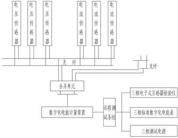
[0021] Such as figure 1 As shown, an electronic sensing type high-voltage metering device and a remote test system, including a voltage sensor, a current sensor, an optical fiber transmission system, a merging unit, and an electric energy metering device, are characterized in that: the voltage sensor and the current sensor The secondary output is a digital optical pulse signal, the signal is transmitted to the merging unit through an optical fiber transmission system, the output optical fiber signals of the voltage sensor and the current sensor are integrated, and then transmitted to the digitizer through an optical cable The electric energy metering device and the digital electric energy metering device are connected to the remote test system. Because the optical fiber has excellent electrical insulation properties and anti-electromagnetic interference characteristics, no additional errors will be introduced in the entire signal transmission process. All voltage sensors and cur...

Embodiment 2

[0027] Such as figure 1 As shown, an electronic sensing type high-voltage metering device and a remote test system, including a voltage sensor, a current sensor, an optical fiber transmission system, a merging unit, and an electric energy metering device, are characterized in that: the voltage sensor and the current sensor The secondary output is a digital optical pulse signal, the signal is transmitted to the merging unit through an optical fiber transmission system, the output optical fiber signals of the voltage sensor and the current sensor are integrated, and then transmitted to the digitizer through an optical cable The electric energy metering device and the digital electric energy metering device are connected to the remote test system. Because the optical fiber has excellent electrical insulation properties and anti-electromagnetic interference characteristics, no additional errors will be introduced in the entire signal transmission process. All voltage sensors and cur...


PUM


Abstract

The invention discloses an electronic sensing type high-voltage metering device and remote testing system. The electronic sensing type high-voltage metering device and remote testing system comprises a voltage sensor, a current sensor, an optical fiber transmission system, a merging unit, a remote testing system and a digitalized electric energy metering device, wherein the secondary outputs of the voltage sensor and the current sensor are digital optical pulse signals which are transmitted to the merging unit through the optical fiber transmission system; optical fiber signals output by the voltage sensor and the current sensor are merged and then are transmitted to the digitalized electric energy metering device through an optical cable; the digitalized electric energy metering device is connected with the remote testing system. The electronic sensing type high-voltage metering device and remote testing system has the beneficial effects that the optical fiber signals output by all the sensors are merged on the side of the sensors and are transmitted to the digital electric energy metering device through the optical cable, a secondary signal transmission loop is simplified, and the site construction workload is greatly reduced.

Description

Technical field [0001] The invention relates to the technical field of electric power metering and testing, in particular to an electronic sensor type high-voltage metering device and a remote testing system. Background technique [0002] With the development of my country’s national economy, it is imperative to build long-distance, large-capacity transmission lines and improve the transmission capacity of transmission lines. For example, new heat-resistant conductors with high voltage and current resistance can be used. However, due to my country’s high-voltage power transmission technology The research and development of the company started late and the application time is short. Therefore, there are still certain technical defects in the field of high-voltage power transmission safety monitoring, and effective online monitoring cannot be completed. [0003] Patent CN201110233321.2 discloses an anti-ferromagnetic resonance self-powered three-phase four-wire electronic transformer ...

Claims


Application Information

Patent Timeline
Patent Type & Authority Applications(China)
IPC IPC(8): G01R22/10G08C23/06
Inventor 林慧刘富荣王忠强辛军禄鹏杨利萍王雪张慧
Owner STATE GRID HENAN ELECTRIC POWER COMPANY ZHENGZHOU POWER SUPPLY
Why Eureka
Try Eureka