A Compact Layout External Cavity Feedback Diode Laser Spectral Synthesis Optical System

A diode laser and external cavity feedback technology, applied in the field of lasers, can solve problems such as the compact and miniaturized design of the laser system, the large focal length of the slow-axis conversion lens, and the limitation of direct application fields, and achieve excellent engineering practical effects, guarantee efficiency and Quality, optimized effect of compact design

Active Publication Date: 2017-06-30
INST OF APPLIED ELECTRONICS CHINA ACAD OF ENG PHYSICS
View PDF5 Cites 0 Cited by
  • Summary
  • Abstract
  • Description
  • Claims
  • Application Information

AI Technical Summary

Problems solved by technology

[0002] Diode lasers have a series of advantages such as high electro-optic efficiency, wide wavelength coverage, small size, light weight, and high reliability. However, the current high-power diode lasers have poor beam quality and large divergence angles, which limit their direct application fields.
Due to the requirement for the spectral width of the synthesized laser, the focal length of the slow-axis conversion lens is often designed to be relatively large, resulting in a relatively large volume of the synthesized system, which is not conducive to the compact and miniaturized design of the laser system

Method used


Image

  • A Compact Layout External Cavity Feedback Diode Laser Spectral Synthesis Optical System
  • A Compact Layout External Cavity Feedback Diode Laser Spectral Synthesis Optical System
  • A Compact Layout External Cavity Feedback Diode Laser Spectral Synthesis Optical System

Examples


Embodiment Construction

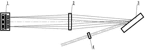
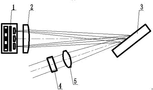
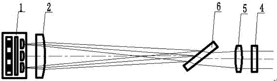
[0020] Such as figure 1 Shown is an ordinary diode laser spectrum synthesis system, which specifically includes a diode laser, a slow-axis conversion cylindrical lens, a reflective plane grating, and an external cavity mirror. Since the diode laser is located on the front focal plane of the slow-axis conversion cylindrical lens, and the reflective plane grating is located on the back focal plane of the slow-axis conversion cylindrical lens, the light emitted by a sub-light-emitting unit in the diode laser is parallel incident after passing through the slow-axis conversion cylindrical lens. to reflective planar gratings. The incident angles of the laser light emitted by different sub-light-emitting units incident on the reflective plane grating are not the same, but because of the different wavelengths, and because of the matching relationship between the incident angle and the wavelength, all the light exits in parallel through the diffraction of the reflective plane grating, ...


PUM


Abstract

The invention discloses an external cavity feedback type diode laser spectrum synthesis optical system with a compact layout, which includes a diode laser, a slow axis conversion cylindrical lens, a diffraction grating, a focusing cylindrical lens and an external cavity mirror, and the diffraction grating is located at the slow axis conversion The rear focal plane of the cylindrical lens; a focusing cylindrical lens is arranged between the external cavity mirror and the diffraction grating, and the focusing cylindrical lens and the slow axis conversion cylindrical lens form a lens group, and the equivalent front focal plane of the lens group is located at The front end of the slow axis conversion cylindrical lens is within one focal length, and the diode laser is located on the equivalent front focal plane of the lens group, and the external cavity mirror is located on the equivalent rear focal plane of the lens group; the laser light emitted by the diode laser passes through the slow axis After converting the cylindrical lens, diffraction grating and focusing cylindrical lens, the beam will exit in parallel and be vertically incident on the external cavity mirror. After being reflected by the external cavity mirror, the laser will return to the original light-emitting unit through the original optical path to form a complete oscillation circuit; The invention reduces the size of the diode laser spectrum synthesis system by nearly half, thereby reducing the overall volume of the laser system and further realizing the compact layout of the system.

Description

technical field [0001] The invention belongs to the technical field of lasers, and in particular relates to an external cavity feedback type diode laser spectrum synthesis optical system with a compact layout. The spectrum synthesis system is more compact and miniaturized than the general external cavity feedback synthesis system. Background technique [0002] Diode lasers have a series of advantages such as high electro-optical efficiency, wide wavelength coverage, small size, light weight, and high reliability. However, the current high-power diode lasers have poor beam quality and large divergence angles, which limit their direct application fields. The use of diode laser spectrum synthesis technology can make the quality of the synthesized beam equal to that of the sub-light-emitting units participating in the synthesis, which makes up for the shortcomings of the poor beam quality of diode lasers, and greatly improves the luminous brightness of diode lasers. Therefore, d...

Claims


Application Information

Patent Timeline
Patent Type & Authority Patents(China)
IPC IPC(8): H01S5/06
Inventor 张卫卢飞李建民田飞陈天江王锋颜宏叶一东关有光谭昊武德勇尹新启雒仲祥邹凯陈黎王树峰
Owner INST OF APPLIED ELECTRONICS CHINA ACAD OF ENG PHYSICS
Why Eureka
Try Eureka