Total heat and latent heat recovery type multi-effect vacuum evaporation and concentration device

A multi-effect vacuum evaporation and concentration device technology, applied in the direction of multi-effect evaporation, evaporator accessories, etc., can solve the problems of waste, insufficient energy utilization, complex process of multi-effect vacuum evaporation and concentration devices, etc., and achieve energy saving and energy saving The effect of hydration

Inactive Publication Date: 2015-05-27
重庆海同医药机械设备制造有限公司
View PDF8 Cites 3 Cited by
  • Summary
  • Abstract
  • Description
  • Claims
  • Application Information

AI Technical Summary

Problems solved by technology

[0003] The technical problem to be solved by the present invention is that the existing multi-effect vacuum evaporation and concentration device is complex in process and wasteful due to insufficient utilization of energy.

Method used


Image

  • Total heat and latent heat recovery type multi-effect vacuum evaporation and concentration device
  • Total heat and latent heat recovery type multi-effect vacuum evaporation and concentration device

Examples


specific Embodiment 1

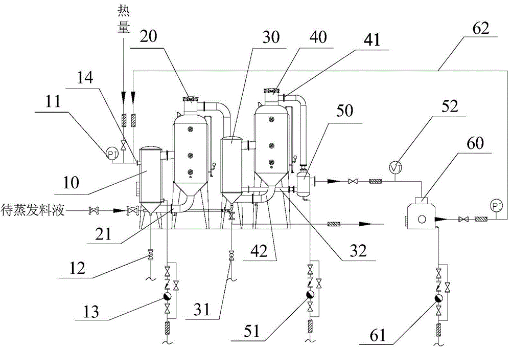
[0022] Such as figure 1 The lower end of the heating layer of the primary heating chamber 10 is connected to the first steam trap 13, the upper left side of the primary heating chamber 10 is provided with a steam inlet 14, and steam enters the heating layer of the primary heating chamber 10 from the steam inlet 14 to provide heat for it The primary heating chamber 10 heats the material liquid to be evaporated, and the steam condensed water formed in the primary heating chamber 10 is regularly discharged through the first steam trap 13 to ensure that the steam in the primary heating chamber 10 is saturated dry steam. The upper end of the primary heating chamber 10 is provided with a steam pressure gauge and a safety valve 11 to ensure heating within a preset pressure value and ensure production safety. The lower ends of the primary heating chamber 10 and the secondary heating chamber 30 are respectively provided with a first cleaning wastewater pipeline 12 and a second cleaning...

specific Embodiment 2

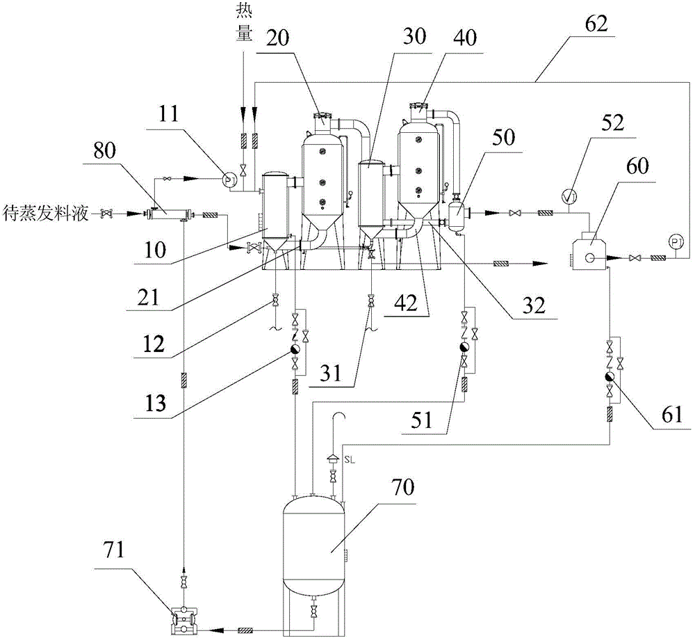
[0027] Such as figure 2 Compared with the specific embodiment 1, a condensate sensible heat recovery device is added. The condensate sensible heat recovery device includes a heat exchanger 80 and a high-temperature condensate recovery tank 70. The heat exchanger 80 is connected to the inlet of the primary heating chamber 10. On the feed liquid pipeline, the first steam trap 13, the second steam trap 51 and the third steam trap 61 are respectively connected to the water inlet of the high-temperature condensate recovery tank 70 through pipelines, and discharge the high-temperature steam condensate to the high-temperature condensate recovery tank 70.

[0028] The water outlet of the high-temperature condensate recovery tank 70 is connected to the heat exchanger 80, and the heat exchanger 80 is provided with a heating layer and a heat-receiving layer, and a delivery pump 71 is provided between the high-temperature condensate recovery tank 70 and the heat exchanger 80. The high-t...


PUM


Abstract

The invention discloses a total heat and latent heat recovery type multi-effect vacuum evaporation and concentration device. A heating chamber and an evaporation chamber are respectively divided into first-stage and second-stage heating chambers and evaporation chambers, and to-be-evaporated feed liquid is fed into a heated layer of the heating chamber by a pipeline; the upper end of a water reception machine is connected with a steam outlet of the second-stage evaporation chamber, a reflow horizontal pipe is arranged between the lower end of the left side of the water reception machine and the second-stage heating chamber, steam and steam condensation water discharged from the second-stage evaporation chamber and a heating layer of a second-stage heater are subjected to steam-water separation in the water reception machine, so that secondary steam and steam condensation water are obtained; and a steam recycling device comprises a vacuum pump and a circulating pipe, the separated secondary steam is pressurized and pumped in a heating layer of the first-stage heating chamber by the vacuum pump so as to provide all or part of a heat source for the first-stage heating chamber. According to the device, secondary steam produced in the process of heating evaporation is pressurized and pumped in the first-stage heating chamber and is used as all or part of heat of the first-stage heating chamber, so that energy is saved, and the recovery of latent heat in negative-pressure secondary steam is realized, so that circulating cooling water for cooling the secondary steam can be saved.

Description

technical field [0001] The invention relates to a multi-effect vacuum evaporation concentration device, in particular to a total heat and latent heat recovery type multi-effect vacuum evaporation concentration device. Background technique [0002] The multi-effect vacuum evaporation and concentration device is the commonly used evaporation and concentration equipment at present. It is used to evaporate and concentrate the feed liquid. Gas-water separation is carried out in the water tank, and the high-temperature steam condensate obtained after separation enters the condensate collection tank, and then circulating cooling water is injected into the interlayer of the condensate collection tank, the high-temperature steam condensate is cooled and discharged, and the steam obtained after separation is condensed , The cooler is treated as condensed water at room temperature and discharged, and the cooled non-condensable gas is vacuum exhausted or entered into other treatments. T...

Claims


Application Information

Patent Timeline
Patent Type & Authority Applications(China)
IPC IPC(8): B01D1/26B01D1/30
CPCY02P70/10
Inventor 卢泽冉张英华
Owner 重庆海同医药机械设备制造有限公司
Why Eureka
Try Eureka