
High-power ultrasonic efficient defoaming device

A defoaming device, ultrasonic technology, applied in the direction of foam dispersion/prevention, etc., can solve problems such as easy adhesion to defoaming equipment, potential safety hazards, general defoaming effect, etc., to eliminate adverse effects, long service life, and eliminate good bubble effect

Active Publication Date: 2015-05-27
山东润蒙应急救援装备有限公司
View PDF6 Cites 1 Cited by
  • Summary
  • Abstract
  • Description
  • Claims
  • Application Information

AI Technical Summary

Problems solved by technology

[0003] 1. Many foams have a certain degree of viscosity. After defoaming, they are easy to adhere to the defoaming equipment. The defoaming equipment needs to be cleaned frequently. This is a heavy workload, and if it is not cleaned in time, it will seriously affect the defoaming effect.
[0004] 2. The above-mentioned defoaming technology generally has a motor as power and many rotating parts, which are easy to wear, low defoaming efficiency, large maintenance, need to replace spare parts, high power consumption, and there are safety hazards
[0005] 3. Exhausting gas requires a separate exhaust system
[0006] 4. The spray defoaming device has complex structure, difficult processing, large gas consumption, and general defoaming effect

Method used


Image

  • High-power ultrasonic efficient defoaming device
  • High-power ultrasonic efficient defoaming device

Examples


Embodiment Construction

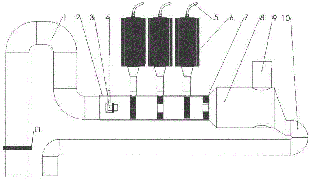
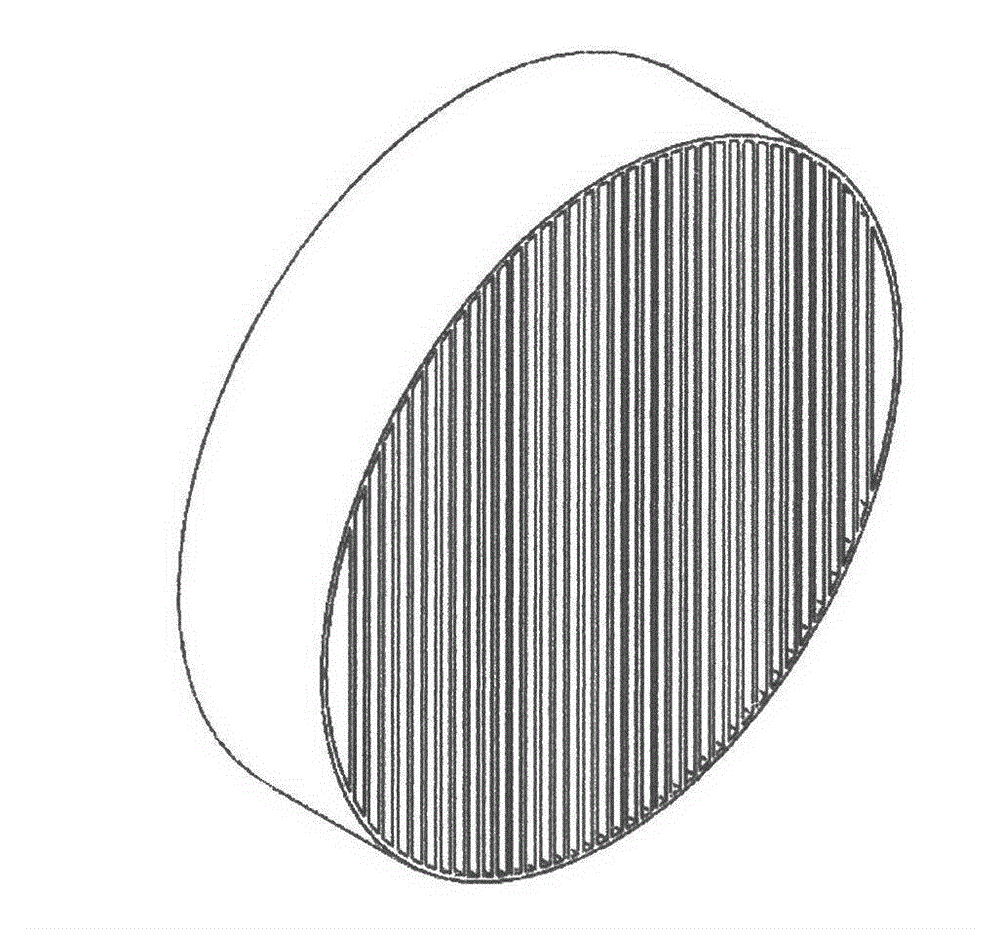
[0030] see figure 1 , which is a structural schematic diagram of Embodiment 1 of the high-power ultrasonic high-efficiency defoaming device of the present invention. As shown in the figure: it includes foam suction pipe 1, power ultrasonic defoamer shell 2, jet aspirator 3, compressed air tube 4, control system signal line 5, acoustic energy converter 6, power ultrasonic defoamer 7, air Liquid collector 8, exhaust pipe 9, liquid return pipe 10, foam sensor 11. The front end of the power ultrasonic defoamer housing 2 is connected to the foam suction pipe 1, and the rear end is connected to the gas-liquid collector 8. Several ultrasonic energy converters 6 are welded on the shell 2 of the power ultrasonic defoamer, and the ultrasonic energy converters 6 receive electrical signals 5 to convert electrical energy into mechanical ultrasonic energy. Several power ultrasonic defoamers 7 are installed inside the shell 2 of the power ultrasonic defoamer. The thickness of the elastic ...


PUM

PropertyMeasurementUnit
thicknessaaaaaaaaaa

Abstract

The invention relates to an efficient defoaming device, in particular to a high-power ultrasonic efficient defoaming device. The high-power ultrasonic efficient defoaming device comprises a foam suction pipe, a power ultrasonic defoamer shell, a jet air ejector, a compressed air pipe, a control system signal line, ultrasonic energy converters, power ultrasonic deformers, a gas-liquid collector, an exhaust pipe, a liquid return pipe and a foam sensor, wherein the front end of the power ultrasonic defoamer shell is connected with the foam suction pipe, and the rear end of the power ultrasonic defoamer shell is connected with the gas-liquid collector; a plurality of ultrasonic energy converters are welded outside the power ultrasonic defoamer shell, and a plurality of power ultrasonic deformers are mounted in the power ultrasonic defoamer shell and correspond to the ultrasonic energy converters at the outside. The high-power ultrasonic efficient defoaming device has the advantages that no rotating component is arranged, the service life is long, no pollution or degeneration exists in the deforming process, and the property of deformed liquid is not influenced; the deforming effect is good, the efficiency is high, and energy consumption is low; the defoaming device is convenient to apply and high in degree of automation and can carry out automatic control and network remote control; the defoaming device is wide in application field and is suitable for all fields of foam production; the use of a defoaming agent is completely avoided, and an adverse effect brought by use of the defoaming agent is eliminated.

Description

technical field [0001] The invention relates to a high-efficiency defoaming device, in particular to a high-power ultrasonic high-efficiency defoaming device. Background technique [0002] In industries such as biological fermentation, beer production, alcohol production, and pharmaceutical antibiotic production, a large amount of foam will be generated in fermentation tanks, reaction kettles, cooking tanks and other equipment during the process, which will cause waste of raw materials and products and prolong the production Reaction cycle, affecting product quality, not conducive to accurate measurement, seriously affecting environmental sanitation and polluting the environment, one of the causes of accidents, and increasing costs. At present, defoamers are commonly used in the process industry to eliminate these foams. However, defoamers are oily chemicals with high COD, which not only increase the cost during use, seriously affect product quality, but also increase the di...

Claims


Application Information

Patent Timeline
Patent Type & Authority Applications(China)
IPC IPC(8): B01D19/02
Inventor 褚兴全褚兴国王超马秀英胡薇
Owner 山东润蒙应急救援装备有限公司
Learn More