Dual-seal-head controllable water heat removing reactor

A double-head, reactor technology, applied in the preparation of carbon monoxide or formate reaction, chemical instruments and methods, inorganic chemistry, etc., can solve problems such as large system resistance, low recovery efficiency of sensible heat and latent heat, and large investment in equipment , to achieve the effect of solving the problem of overheating

Active Publication Date: 2015-05-27
NANJING DUNXIAN CHEM TECH
View PDF4 Cites 17 Cited by
  • Summary
  • Abstract
  • Description
  • Claims
  • Application Information

AI Technical Summary

Problems solved by technology

This indirect heat exchange recovery transformation system has low thermal energy grade, low recovery efficiency of sensible heat and latent heat, easy overheating of the catalyst, simultaneous transformation and side reactions such as methanation, etc.
[0003] Coal-to-ethylene glycol carbonylation reactor currently uses a ф25X2 tube to fill the catalyst, and water outside the tube to remove heat. A column and tube reactor is composed of thousands of axial ф21 cylindrical catalyst beds, and the gas distribution is uneven. Uniformity, many side reactants, large catalyst bed resistance, large thermal stress, equipment leakage, a 200,000-ton/year ethylene glycol plant carbonylation reactor requires 6 shell-and-tube reactors to operate in parallel, and the project investment major defect
[0004] The esterification hydrogenation reactor for coal-to-ethylene glycol currently uses ф38X2 tubes to fill catalysts, and water outside the tubes to remove heat. A column-tube reactor is composed of thousands of axial ф34 cylindrical catalyst beds, and the gas distribution Inhomogeneity, many side reactants, la...

Method used


Image

  • Dual-seal-head controllable water heat removing reactor

Examples


Embodiment Construction

[0029] The embodiments of the present invention are described in detail below. This embodiment is implemented on the premise of the technical solution of the present invention, and detailed implementation methods and specific operating procedures are provided, but the protection scope of the present invention is not limited to the following implementation example.

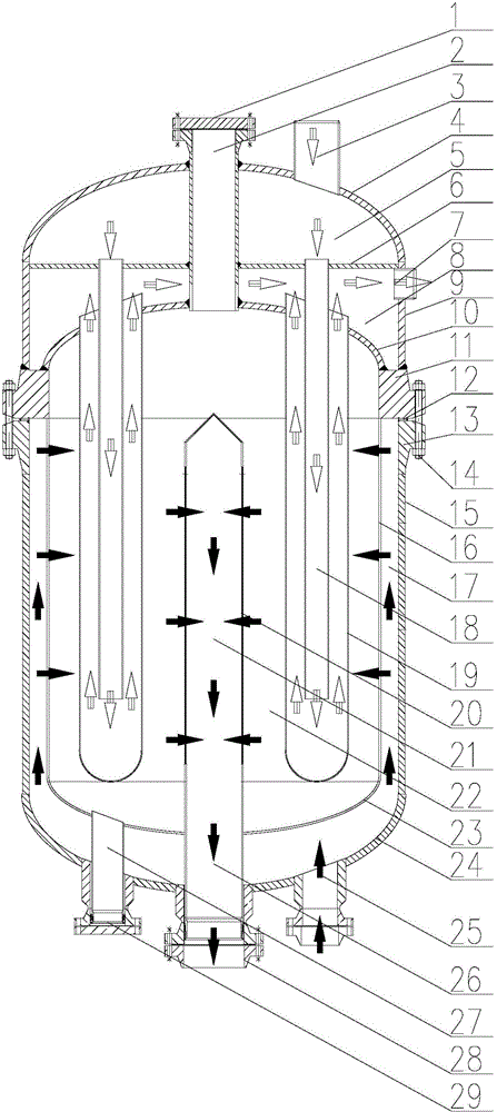
[0030] Such as figure 1 As shown, this embodiment includes a catalyst filling pipe 2, a water inlet pipe 3, an upper and outer sealing head 4, a partition 6, a water outlet pipe 7, a plurality of water guide pipes 18, a plurality of heat exchange pipes 19, an upper inner sealing Head 10, upper flange 11, gas distribution cylinder 16, gas collecting cylinder 20, lower inner head 23 and catalyst self-unloading pipe 27, lower flange 13 connected as one, main cylinder body 15, lower outer head 24, catalyst Self-unloading port 29, air inlet 25 and air outlet 28;

[0031] The water inlet pipe 3 is set on the top of the...


PUM


Abstract

The invention discloses a dual-seal-head controllable water heat removing reactor. The top of a main cylinder body is connected with a lower flange; the bottom of the main cylinder body is connected with a lower outer seal head; the upper flange is connected with the lower flange; one end of a catalyst filling pipe is connected between an upper inner seal head and a gas distribution cylinder, and the other end of the catalyst filling pipe sequentially penetrates through a baffle and an upper external seal head; one end of a water guide pipe is communicated between the baffle and the upper outer seal head, and the other end of the water guide pipe sleeves a heat exchange pipe internally; a pipe body of the heat exchange pipe is positioned in a gas distribution cylinder; an outlet of the heat exchange pipe is formed between the baffle and the upper inner seal head; a cylinder body of a gas collecting cylinder is positioned in the gas distribution cylinder; an outlet of the gas collecting cylinder is connected with a gas outlet. The heat exchange pipe is buried in a catalyst bed layer so as to remove reaction heat in the catalyst bed layer timely, and the defects of short service life, easiness in overtemperature, multiple auxiliary reactants, difficulty in bed layer temperature control, long driving time, difficulty of scaling up, high running energy consumption, high project investment and the like in the prior art can be solved.

Description

technical field [0001] The invention relates to a fixed-bed catalyst, a conversion, synthesis and hydrogenation reactor in a gas phase state, in particular to a double-head controllable water transfer heat reactor. Background technique [0002] The CO shift reactor is a widely used reactor in the chemical industry. During this period, people have made many improvements to the shift reactor, from the original full axial to full radial, and achieved good results in the resistance of the catalyst bed. effect, but the catalyst bed is still an adiabatic reaction. The catalyst bed is divided into several beds, and indirect heat exchange or water cooling is adopted between each bed. This kind of indirect heat exchange recovery transformation system has the disadvantages of low thermal energy grade, low recovery efficiency of sensible heat and latent heat, easy overheating of the catalyst, simultaneous transformation and side reactions such as methanation, etc. [0003] Coal-to-eth...

Claims


Application Information

Patent Timeline
IPC IPC(8): B01J8/02C01B3/16C10G2/00C07C69/36C07C67/36C07C31/20C07C29/149C07C31/04C07C27/04C07C1/04C07C9/04
CPCB01J8/02B01J8/0285B01J2208/00132C01B3/16C01B2203/0833C01B2203/0894C10G2/32
Inventor 王庆新郑高潮凡殿才高明林王揽月
Owner NANJING DUNXIAN CHEM TECH
Why Eureka
Try Eureka