Eureka AIR delivers breakthrough ideas for toughest innovation challenges, trusted by R&D personnel around the world.

Aluminum alloy side milling process under assistance of ultrasonic longitudinal vibration

A longitudinal vibration and ultrasonic technology, applied in the field of mechanical processing, can solve the problems of immature production and limit the application scope of ultrasonic vibration-assisted milling technology, and achieve the effect of easy to be widely used, mature production technology, and inhibition of sticking.

Inactive Publication Date: 2015-05-27
CENT SOUTH UNIV
View PDF5 Cites 5 Cited by
  • Summary
  • Abstract
  • Description
  • Claims
  • Application Information

AI Technical Summary

Problems solved by technology

However, most ultrasonic vibration-assisted milling processes apply ultrasonic vibrations to the workpiece, which limits the application range of ultrasonic vibration-assisted milling processes; there are also very few ultrasonic vibration-assisted milling processes that use ultrasonic torsional vibration transducers, and Ultrasonic torsional vibration is applied to the tool holder, such as the Chinese patent application: "A method of ultrasonic torsional vibration side milling combined with tension clamping" (application number 201210414295.8, publication number CN102922014A) introduces a combination of tension clamping Ultrasonic torsional vibration side milling method
An ultrasonic torsional vibration transducer is used in this method, however, the production of such torsional vibration transducers is currently immature

Method used


Image

  • Aluminum alloy side milling process under assistance of ultrasonic longitudinal vibration
  • Aluminum alloy side milling process under assistance of ultrasonic longitudinal vibration

Examples


Embodiment Construction

[0014] The present invention will be further described below in conjunction with the accompanying drawings.

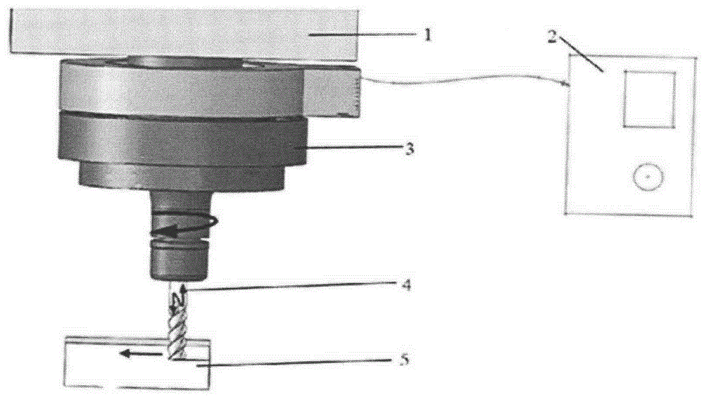
[0015] Such as figure 1 As shown, the device required by the present invention is composed of a common machine tool 1, an ultrasonic generator 2, an ultrasonic longitudinal vibration tool holder 3, a helical end mill 4, and a workpiece 5. Driven by the ultrasonic longitudinal vibration tool holder 3, the helical end mill 4 performs ultrasonic longitudinal vibration. When the tool is side milling, in addition to the rotational motion and the motion in the feed direction, it also undergoes ultrasonic vibration in the axial direction. The process device of the present invention is composed of an ultrasonic generator, an ultrasonic longitudinal vibrating tool holder and a common machine tool. Except that the tool movement mode is different from the common side milling process, other things such as cooling liquid are the same as the common side milling process. The specif...


PUM


Abstract

The invention relates to an aluminum alloy side milling process under assistance of ultrasonic longitudinal vibration. A process device consists of an ultrasonic wave generator, an ultrasonic longitudinal vibration cutter handle and an ordinary machine tool. The process comprises the following steps: (1) selecting a cutter for side milling, and installing the cutter onto the ultrasonic longitudinal vibration cutter handle; (2) starting the machine tool, installing the ultrasonic longitudinal vibration cutter handle onto the machine tool, and well fixing a workpiece; (3) starting the ultrasonic wave generator, wherein the ultrasonic longitudinal vibration frequency of the cutter is 20kHz to 40kHz, the ultrasonic longitudinal vibration amplitude value is 0 to 20 micrometers, setting a machining process parameter, and beginning the side milling; and (4) closing the ultrasonic wave generator and the machine tool after the side milling is ended, and taking down the ultrasonic longitudinal vibration cutter handle and the well machined workpiece. The aluminum alloy side milling process has beneficial effects that the process flow is easy to realize, the cutter sticking phenomenon is improved, and the milling quality of the workpiece surface such as the surface coarseness is better than the surface quality of the ordinary milling.

Description

technical field [0001] The invention relates to a milling process, in particular to an ultrasonic longitudinal vibration-assisted side milling aluminum alloy process, which belongs to the technical field of mechanical processing. Background technique [0002] Aluminum alloy not only has low density, strong specific ratio, good electrical and thermal conductivity, but also has good mechanical processability and corrosion resistance. It has been widely used in aviation, automobile, petrochemical, electronic and telecommunications industries. However, the material of aluminum alloy is relatively soft and has a large shape. When using traditional milling technology to process aluminum alloy, it is easy to stick to the tool, and built-up edge is easy to form on the tool, which affects the machining accuracy and roughness of the workpiece surface. In order to improve the above problems, ultrasonic vibration assisted machining technology came into being. Ultrasonic vibration-assis...

Claims


Application Information

Patent Timeline
Patent Type & Authority Applications(China)
IPC IPC(8): B23C3/00
CPCB23C3/00B06B1/02
Inventor 蔺永诚隆志力刘延星
Owner CENT SOUTH UNIV
Why Eureka
Eureka Blog
Learn More