Supercharge Your Innovation With Domain-Expert AI Agents!

Three-section heat exchange type warm air furnace

A heater, heat exchange technology, applied in the field of three-stage heat exchange energy-saving heater, can solve the problems of short contact time of cold air heating surface, high furnace surface temperature, unusable heat, etc., to achieve the guarantee Efficient heat exchange state, high heat exchange efficiency and simple structure

Active Publication Date: 2015-05-27
SHENYANG AGRI UNIV
View PDF7 Cites 0 Cited by
  • Summary
  • Abstract
  • Description
  • Claims
  • Application Information

AI Technical Summary

Problems solved by technology

However, due to the design of the structure of the existing air heater, it also has the following technical problems: the surface temperature of the furnace body is high, even reaching the degree of red heat, which emits a large amount of heat, causing a large amount of heat loss; the cold air and the heating surface inside the furnace The contact time is short, the area is small, the heat exchange is insufficient, and the heat utilization efficiency is low; when the furnace is pressed at night (slow combustion), the heat generated by the burning fuel near the furnace bar at the bottom of the furnace cannot be used, resulting in low heat utilization efficiency ; The tar and carbon deposits on the inner wall of the heat exchanger and on the surface of the heat exchange tube cannot be removed; the existing heater can only be used for heating only, and has no cooking function

Method used


Image

  • Three-section heat exchange type warm air furnace
  • Three-section heat exchange type warm air furnace
  • Three-section heat exchange type warm air furnace

Examples


Embodiment Construction

[0021] In order to make the objectives, technical solutions, and advantages of the present invention clearer, the following further describes the present invention in detail with reference to the accompanying drawings and embodiments. It should be understood that the specific embodiments described here are only used to explain the present invention, but not to limit the present invention.

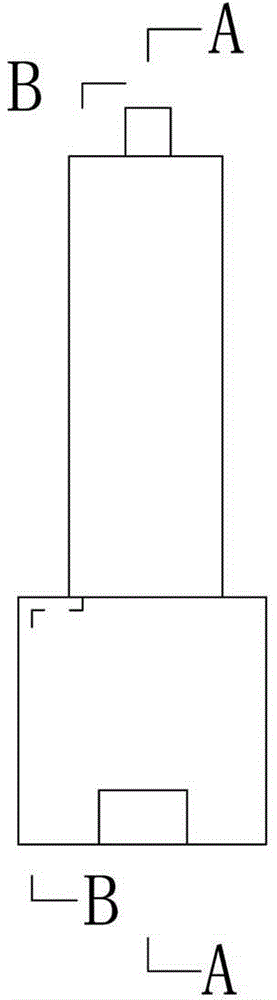
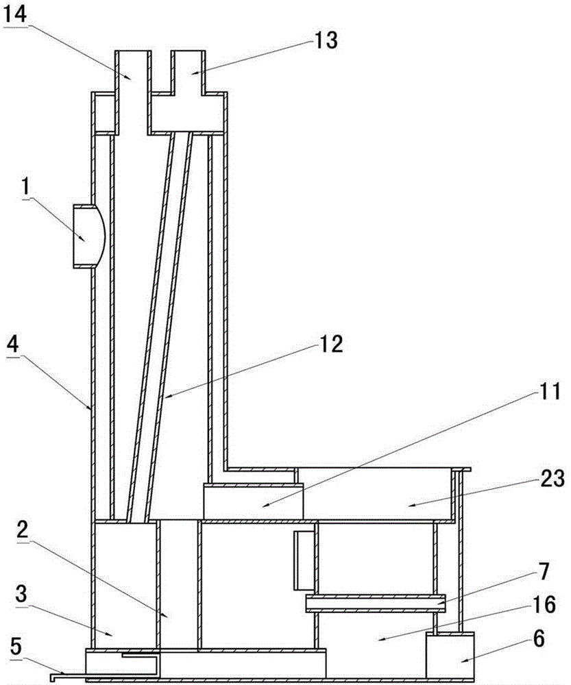
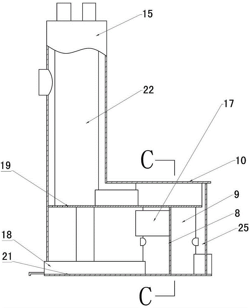
[0022] Such as figure 1 , figure 2 with image 3 As shown, the three-stage heat exchange heater and the three-stage heater heater of the present invention include a slag outlet 6, a grate bar 7, an upper hearth 23, a lower hearth 9, a fire throat 11, and a smoke outlet 14, Heat exchanger 15, heating chamber 16, base 21, and outer shell 24. The heat exchanger 15 is an inner and outer double-layer cylinder structure. The cold air inlet 1 is opened on the heat exchanger outer cylinder 4, which is close to the combustion furnace. One side is shorter than the other side, and the short position ins...


PUM


Abstract

The invention relates to heat supply equipment, in particular to a three-section heat exchange type warm air furnace. The three-section heat exchange type warm air furnace comprises a fire bar, a hearth, a fire throat, a heat exchanger, a warm air chamber and a shell, wherein the heat exchanger is an inner / outer two-layer cylinder structure; a cold air inlet is formed in an outer cylinder of the heat exchanger; one side of the outer cylinder of the heat exchanger is shorter than the other side; the short inner side position of the outer cylinder of the heat exchanger is in closed connection with a furnace stage board; a sandwich layer between the inner cylinder and the outer cylinder of the heat exchanger is communicated with an upper hearth sandwich layer through the blockage of a spacing plate; the upper hearth sandwich layer and a lower hearth sandwich layer are communicated at the front end of the hearth; side stand plates are respectively and symmetrically arranged below sandwich layers at the two sides of a lower hearth; the lower hearth sandwich layer is divided into a transition chamber and a buffer chamber by the side stand plates; the fire bar is a hollow fire bar; and two ports of the fire bar are respectively communicated with the transition chamber and the buffer chamber. The three-section heat exchange type warm air furnace has the advantages of simple structure, high heat exchange efficiency, sufficient fuel combustion, low smoke discharge, energy conservation and environmental protection.

Description

Technical field [0001] The invention relates to a heating equipment, in particular to a three-stage heat exchange type energy-saving heater. Background technique [0002] The heater is a professional heating equipment that uses hot air as a medium and carrier, which can greatly improve the heat utilization rate and heat work effect. The structure of the heater is a combination of a combustion furnace and a heat exchanger, which can burn coal and other fuels. The heater has the characteristics of simple operation, good heating effect, high safety factor, etc., and it is widely used in the field of space heating or air heating by all walks of life. However, due to the structural design of the existing heating stove, it still has the following technical problems: the surface temperature of the furnace body is high, even reaching the level of red heat, dissipating a large amount of heat, causing a large amount of heat loss; cold air and the heating surface inside the furnace The c...

Claims


Application Information

Patent Timeline
IPC IPC(8): F24H3/06F24H9/18
Inventor 李浦马凤鸣李泉海张凤武张守忠
Owner SHENYANG AGRI UNIV
Features
  • R&D
  • Intellectual Property
  • Life Sciences
  • Materials
  • Tech Scout
  • Unparalleled Data Quality
  • Higher Quality Content
  • 60% Fewer Hallucinations
Learn More