Photoelectric oscillator based on optical resonant cavity

A technology of optical resonator and photoelectric oscillator, applied in the direction of solid-state lasers, etc., can solve the problems of high Q value and single-mode output, side-mode noise and difficult filter filtering, and limit the practical application of photoelectric oscillators, etc., to achieve Achieve miniaturization and integration, highly stable single-mode oscillation, and promote the effect of marketization

Inactive Publication Date: 2015-05-27
ZHONGBEI UNIV
View PDF5 Cites 18 Cited by
  • Summary
  • Abstract
  • Description
  • Claims
  • Application Information

AI Technical Summary

Problems solved by technology

But the current long fiber optic oscillator has certain defects: 1) High Q value and single-mode output are contradictory
2) External environmental factors such as temperature, mechanical vibration, etc. will affect some optoelectronic devices and loop length of the optoelectronic oscillator
3) The discrete optoelectronic devices of optoelectronic oscillators are not easy to miniaturize, which limits the practical application of optoelectronic oscillators
4) The feedback loop composed of long optical fibers will generate a large number of side modes with small frequency intervals, resulting in gain competition between side modes and main modes, but these side mode noises are difficult to filter out by point filters

Method used


Image

  • Photoelectric oscillator based on optical resonant cavity
  • Photoelectric oscillator based on optical resonant cavity
  • Photoelectric oscillator based on optical resonant cavity

Examples


Embodiment Construction

[0024] The present invention will be further described below in conjunction with accompanying drawing:

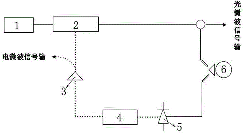
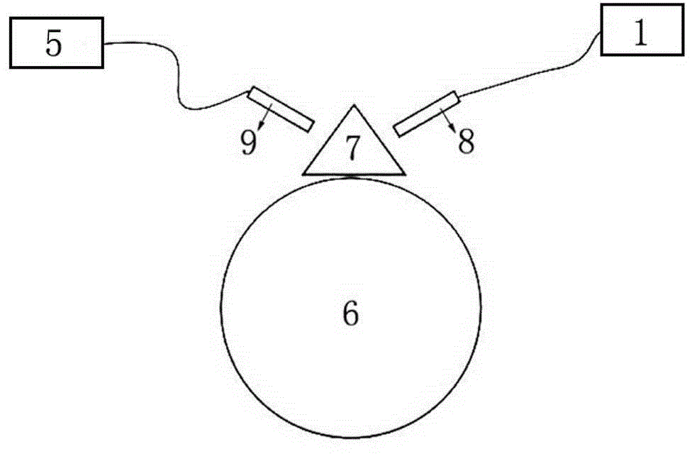
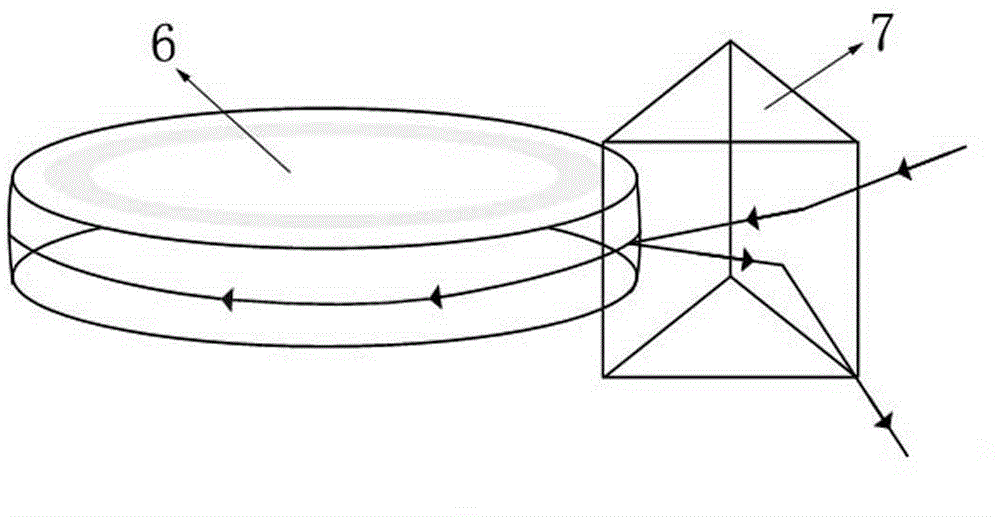
[0025] like Figure 1 to Figure 3 As shown, an optoelectronic oscillator based on an optical resonator includes a laser 1, an electro-optic modulator 2, an amplifier 3, a filter 4, a photodetector 5 and an optical resonator 6; wherein, the laser 1 and the electro-optic modulator 2 The input end is connected, the output end of the electro-optic modulator 2 is connected with the input end of the optical resonant cavity 6, the output end of the optical resonant cavity 6 is connected with the input end of the photodetector 5, the output end of the photodetector 5 is connected with the input end of the filter 4 The input end is connected, the output end of the filter 4 is connected with the input end of the amplifier 3, the output end of the amplifier 3 is connected with the output end of the electro-optic modulator 2; the laser 1, the electro-optic modulator 2, the amplifier 3,...


PUM


Abstract

The invention discloses a photoelectric oscillator based on an optical resonant cavity, and aims to carry out photoelectric oscillation on laser so as to generate high-quality microwave signals. The photoelectric oscillator consists of a laser, a photoelectric modulator, an amplifier, a filter, a photoelectric detector and an optical resonant cavity which form a loop, wherein the loop forms the main structure of the photoelectric oscillator. The photoelectric oscillator disclosed by the invention has outstanding advantages in generating high-quality microwave signals in a light domain, and high-quality microwave signals can be formed through multiple times of oscillation; the optical resonant cavity is adopted to output the microwave signals through multiple times of oscillation, and the invention mainly aims to minimize the photoelectric oscillator; the optical resonant cavity is adopted to replace conventional long optical fibers, so that the photoelectric oscillator has the characteristics of small size, low consumption, stable performance and the like, and is applicable to the field of radio wireless communication and microwave photonics; the optical resonant cavity is realized through coupled prisms and micro disc cavities and thus is relatively stable in property when being compared with an optical resonant cavity realized through coupled waveguide and micro discs.

Description

technical field [0001] The invention relates to a photoelectric oscillator, in particular to a photoelectric oscillator based on an optical resonant cavity, and belongs to the technical field of microwave and optoelectronics. Background technique [0002] Optoelectronic oscillator (OEO: Optoelectronic oscillator) is a high-performance microwave signal generating device. Relying on the development of microwave photonics, optoelectronic oscillators use optoelectronic feedback loop technology to convert laser energy into microwave signal energy. Compared with traditional oscillators, optoelectronic oscillators have extremely low phase noise, and get rid of the limitation that the phase noise performance of traditional microwave oscillators will decrease with the increase of frequency, and can output stable low noise in both optical and electrical forms signal, becoming a new type of high-quality microwave signal source. The optoelectronic oscillator not only has a certain tun...

Claims


Application Information

Patent Timeline
Patent Type & Authority Applications(China)
IPC IPC(8): H01S1/02
Inventor 薛晨阳闫树斌卢晓云刘俊张文栋王永华郑华刘耀英
Owner ZHONGBEI UNIV
Why Eureka
Try Eureka