Anisotropic conductive adhesive

A conductive adhesive, anisotropic technology, used in conductive adhesives, adhesives, conductive materials, etc., can solve problems such as poor connection reliability, and achieve the effect of high heat release and increased contact area

Active Publication Date: 2015-05-27
DEXERIALS CORP
View PDF9 Cites 16 Cited by
  • Summary
  • Abstract
  • Description
  • Claims
  • Application Information

AI Technical Summary

Problems solved by technology

like Figure 7 , 10 As shown, when the electrodes are joined with the conductive paste 303a, 303b, heat can be efficiently released, but as described above, the connection reliability of the connection using the conductive paste 303a, 303b is poor.
Additionally, if Figure 9 As shown, in the case of gold-tin eutectic bonding, the same as above, the connection reliability is also poor

Method used


Image

  • Anisotropic conductive adhesive
  • Anisotropic conductive adhesive
  • Anisotropic conductive adhesive

Examples


Embodiment 1

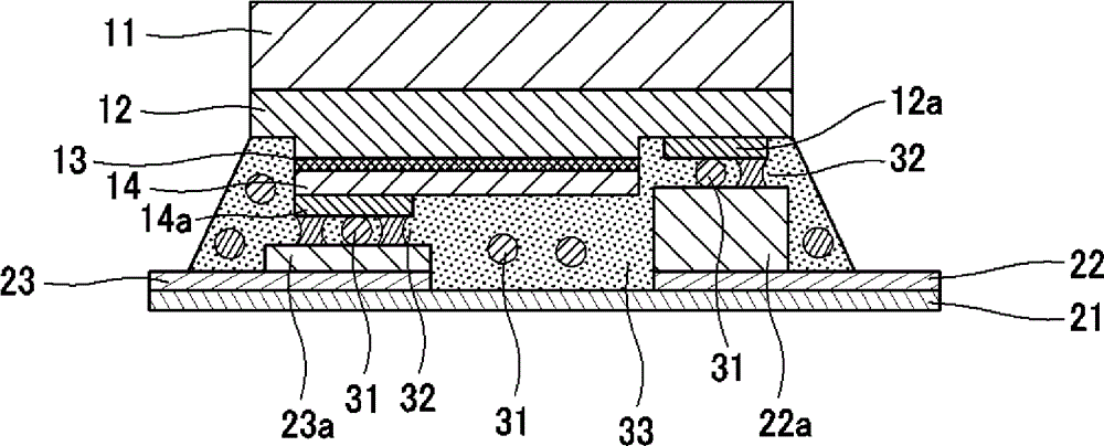
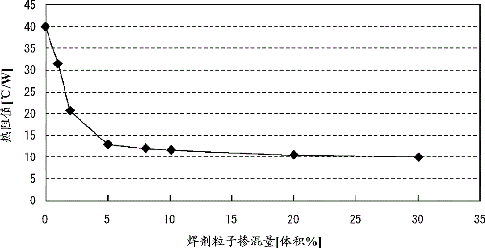
[0093] 8 volume % of conductive particles and 2 volume % of solder particles were mixed with the aforementioned resin composition to prepare an anisotropic conductive adhesive having thermal conductivity. The thermal resistance measurement result of the LED package produced using this anisotropic conductive adhesive was 21.0° C. / W, and the chip shear strength was 26 N / chip. In addition, the evaluation results of the high-temperature and high-humidity test for electrical characteristics are ○ at the initial stage and ○ after the test; and the evaluation results of the thermal shock test for electrical characteristics are ○ at the initial stage and ○ after the test. .

Embodiment 2

[0095] 5% by volume of conductive particles and 5% by volume of solder particles were mixed with the aforementioned resin composition to prepare an anisotropic conductive adhesive having thermal conductivity. The thermal resistance measurement result of the LED package produced using this anisotropic conductive adhesive was 13.2° C. / W, and the chip shear strength was 37 N / chip. In addition, the evaluation results of the high-temperature and high-humidity test for electrical characteristics are ○ at the initial stage and ○ after the test; and the evaluation results of the thermal shock test for electrical characteristics are ○ at the initial stage and ○ after the test. .

Embodiment 3

[0097] 2% by volume of conductive particles and 8% by volume of solder particles were mixed with the aforementioned resin composition to prepare an anisotropic conductive adhesive having thermal conductivity. The thermal resistance measurement result of the LED package prepared using this anisotropic conductive adhesive was 12.2° C. / W, and the chip shear strength was 45 N / chip. In addition, the evaluation results of the high-temperature and high-humidity test for electrical characteristics are ○ at the initial stage and ○ after the test; and the evaluation results of the thermal shock test for electrical characteristics are ○ at the initial stage and ○ after the test. .


PUM

PropertyMeasurementUnit
particle sizeaaaaaaaaaa

Abstract

Provided is an anisotropic conductive adhesive which is capable of achieving high heat dissipation performance. Conductive particles (31) and solder particles (32) are dispersed in a binder. In an LED package which is obtained by thermal compression bonding using this anisotropic conductive adhesive, terminals (electrodes (12a, 14a)) of an LED element and terminals (electrodes (22a, 23a)) of a substrate are electrically connected with each other through the conductive particles (31), while the terminals of the LED element and the terminals of the substrate are solder-joined with each other.

Description

technical field [0001] The present invention relates to an anisotropic conductive adhesive in which conductive particles are dispersed, and more particularly to an anisotropic conductive adhesive capable of dissipating heat from chips (elements) such as driver ICs (integrated circuits) and LEDs (light-emitting diodes). glue. [0002] This application claims priority based on Japanese Patent Application No. Japanese Patent Application No. 2012-210224 for which it applied in Japan on September 24, 2012, and takes in this application by referring this application. Background technique [0003] Conventionally, a wire-bonding construction method has been employed as a construction method for mounting an LED element on a substrate. Such as Figure 6 As shown, the wire bonding construction method is that the electrodes of the LED element (the first conductivity type electrode 104a and the second conductivity type electrode 102a) face up (face up), and the LED element is performed ...

Claims


Application Information

Patent Timeline
Patent Type & Authority Applications(China)
IPC IPC(8): C09J201/00C09J9/02C09J11/02H01B1/00H01B1/22H01B5/16H01L21/60
CPCB23K35/025B23K35/24B23K35/36C08K9/02C08K2201/001C09J9/02C09J11/00H01B1/22H01L23/3737H01L24/05H01L24/06H01L24/13H01L24/16H01L24/29H01L24/32H01L24/81H01L33/62H01L2224/0401H01L2224/06102H01L2224/16238H01L2224/1703H01L2224/17051H01L2224/2919H01L2224/293H01L2224/32225H01L2224/48091H01L2224/49107H01L2224/73204H01L2224/73265H01L2224/81193H01L2224/81805H01L2224/81903H01L2224/8385H01L2224/83851H01L2224/9211H01L2924/01322H01L2924/07811H01L2924/12041H01L2924/15787H01L2924/00014H01L2224/16225H01L2924/00H01L2924/014H01L2224/81H01L2224/83H01L2924/00015B23K1/0016H01L23/5328H05K3/3485H05K13/0465
Inventor 石神明蟹泽士行波木秀次青木正治
Owner DEXERIALS CORP
Why Eureka
Try Eureka