Central air conditioner fresh air handling unit structure and operating method thereof
A fresh air unit and centralized air-conditioning technology, applied in air-conditioning systems, space heating and ventilation, space heating and ventilation details, etc., can solve the problem of less than 30% power generation efficiency, gas cannot be directly used indoors, and reduce input Issues such as energy utilization rate, to achieve rapid response to changes in cooling and heating loads, flexible processing and adjustment, simple equipment and operation adjustment
- Summary
- Abstract
- Description
- Claims
- Application Information
AI Technical Summary
Problems solved by technology
Method used
Image
Examples
Embodiment 1
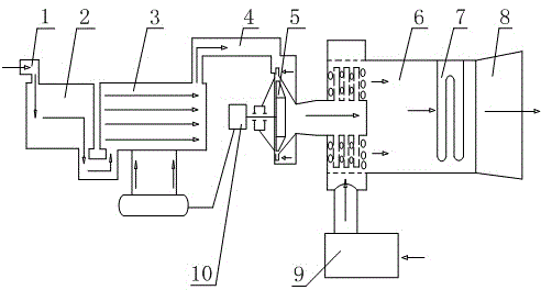
[0026] Such as figure 1As shown, a central air-conditioning fresh air unit structure includes a gas delivery device, the gas delivery device is connected to an expander 5 , the expander 5 is connected to a mixer 6 , and the mixer 6 is connected to a heater 7 . This technical solution is relatively large-scale use, and is also suitable for use in areas such as drying, refrigeration, and freezing with compressed air sources, or in large-area and large-space environments such as office buildings and shopping malls, just like the use environment of central air conditioning, air transmission The device inputs high-pressure air, which can either pressurize the air itself, or directly serve as a channel for high-pressure air outside. Expanders are usually used in cryogenic equipment. The high-pressure air acts on the expander to achieve the purpose of cooling. The mixer 6 mixes the low-temperature mainstream air and the secondary air, and adjusts the moisture content of the mixed ai...
Embodiment 2
[0028] Such as figure 1 As shown, the gas transmission device includes a compressor 2, an evaporator 3, and a dryer 4 connected in sequence. The dryer 4 is connected to an end of the expander 5 away from the mixer 6. The expander 5 is connected to a generator set 10, and the generator set 10 is connected with the evaporator 3, and the end of the mixer 6 away from the expander 5 is connected with a secondary blower unit 9. The air compressor 2, the evaporator 3 and the drier 4 are all existing equipment, which are all used in the existing centralized air conditioners.
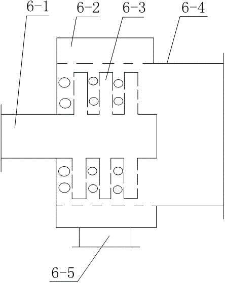
[0029] Such as figure 2 As shown, the mixer 6 includes a main flow inlet pipe 6-1, a secondary flow inlet passage 6-2, a main flow branch pipe 6-3, a mixing chamber 6-4 and a secondary flow inlet pipe 6-5, and the main flow inlet pipe 6- 1. One end is set in the mixing chamber 6-4, and the other end protrudes from the mixing chamber 6-4 to connect with the expander 5. The main branch pipe 6-3 is fixed on the ...
Embodiment 3
[0046]A working method of a central air-conditioning fresh air unit, using a water-cooled or air-cooled compressor 2 with an outlet air pressure of 3-6 atmospheres and an outlet air temperature of 35°C-45°C to compress the air and then input the air into the evaporator 3 to form the mainstream Air, the mainstream air is cooled in the evaporator 3, and the evaporator 3 reduces the temperature of the air discharged from the compressor 2 to 5-20 degrees Celsius; the low-temperature mainstream air output from the evaporator 3 is dried by the dryer 4, and the dryer 4 It is used to remove the liquid droplets in the low-temperature mainstream air, reduce the moisture content of the low-temperature mainstream air, and thus reduce the damage to the equipment caused by the freezing of liquid droplets in the expansion process of the expander 5; the low-temperature mainstream air after passing through the dryer 4 enters The expander 5 expands and cools down again. The air temperature at th...
PUM
 Abstract
Description
Claims
Application Information
 - R&D
- Intellectual Property
- Life Sciences
- Materials
- Tech Scout
- Unparalleled Data Quality
- Higher Quality Content
- 60% Fewer Hallucinations
Browse by: Latest US Patents, China's latest patents, Technical Efficacy Thesaurus, Application Domain, Technology Topic, Popular Technical Reports.
© 2025 PatSnap. All rights reserved.Legal|Privacy policy|Modern Slavery Act Transparency Statement|Sitemap|About US| Contact US: help@patsnap.com


