
Remote control system for household robot

A remote control system, robot technology, applied in general control system, control/adjustment system, computer control, etc., can solve the problems of remote real-time control function to be perfected, automatic detection and control of indoor environment, rising labor cost, etc., to achieve convenience The effects of popularization and use, simple structure and high control reliability

Inactive Publication Date: 2015-06-03
XIAN ZHONGKEMAITE ELECTRONICS TECH EQUIP
View PDF0 Cites 13 Cited by
  • Summary
  • Abstract
  • Description
  • Claims
  • Application Information

AI Technical Summary

Problems solved by technology

[0002] In recent years, with the rapid development of computer technology and artificial intelligence science, intelligent robot technology has gradually become a hot spot in the field of modern robot research. Among them, service robots have opened up a new field of robot applications. There are three main reasons for the emergence of service robots: First, Rising labor costs; second, humans want to do boring manual labor, such as cleaning, housework, etc.; third, the aging population and the improvement of the social welfare system also provide a wide range of market application prospects for some service robots; used in households The service robot is a combination of mechanics, electronic technology, sensing technology, control technology, image recognition and artificial intelligence and many other disciplines. It has intelligent characteristics such as intelligent control and automatic operation. However, existing robots can only Simple action instructions cannot complete the function of automatic detection and control of the indoor environment alone, and there are still certain safety hazards, and it is impossible to call the police or contact the user in an emergency when there is a dangerous environment. The remote real-time control function needs to be improved.

Method used


Image

  • Remote control system for household robot

Examples


Embodiment Construction

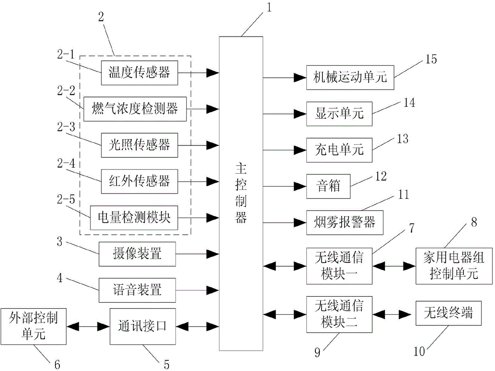
[0023] Such as figure 1 As shown, the present invention includes a main controller 1 and a household appliance group control unit 8 connected with the main controller 1, a wireless terminal 10 and an external control unit 6, and the household appliance group control unit 8, the wireless terminal 10 and the external control unit The unit 6 and the main controller 1 are respectively connected to the external control unit 6 through the wireless communication module 1 7, the wireless communication module 2 9, and the input terminal of the main controller 1 is connected with the detection unit 2 and the setting Above the eyes of the robot, there is an imaging device 3 for photographing and recording indoor conditions and a voice device 4 for transmitting voice calls from robots and sounds from household appliances. The detection unit 2 includes a temperature sensor 2-1 for detecting indoor temperature. The gas concentration detector 2-2 for detecting whether the indoor gas exceeds ...


PUM


Abstract

The invention discloses a remote control system for a household robot. The remote control system comprises a main controller, and a household appliance group control unit, a wireless terminal and an external control unit which are connected with the master controller; the input end of the master controller is connected with a detection unit, a photographic device and a voice device; the detection unit comprises a temperature sensor, a gas concentration detector, an illumination sensor, an infrared sensor and an electric quantity detection module; the output end of the master controller is connected with a mechanical motion unit for controlling the motion of the robot, a charging unit and a smoke alarm; the output end of the master controller is also connected with a sound box and a display unit. The remote control system can be used for judging whether the environment is safe and gives an alarm to the unsafety situation, can be used for carrying out remote real-time communication and control with a user, and is high in control reliability, high in working stability, long in service life, strong in practicability, good in using effect and convenient to popularize and use.

Description

technical field [0001] The invention relates to the technical field of robot automatic control, in particular to a remote control system for a household robot. Background technique [0002] In recent years, with the rapid development of computer technology and artificial intelligence science, intelligent robot technology has gradually become a hot spot in the field of modern robot research. Among them, service robots have opened up a new field of robot applications. There are three main reasons for the emergence of service robots: First, Rising labor costs; second, humans want to do boring manual labor, such as cleaning, housework, etc.; third, the aging population and the improvement of the social welfare system also provide a wide range of market application prospects for some service robots; used in households The service robot is a combination of mechanics, electronic technology, sensing technology, control technology, image recognition and artificial intelligence and ma...

Claims


Application Information

Patent Timeline
IPC IPC(8): G05B19/418
CPCG05B19/04G05B15/02
Inventor 李晓萍
Owner XIAN ZHONGKEMAITE ELECTRONICS TECH EQUIP
Learn More