A non-contact transformer

A non-contact and transformer technology, applied in the direction of transformers, fixed transformers, transformer/inductor cores, etc., can solve the problem of loss of power transmission capacity, and achieve the goal of avoiding no power transmission, improving power transmission capacity, and compensating power transmission Effect

Active Publication Date: 2017-05-03
NANJING UNIV OF AERONAUTICS & ASTRONAUTICS
View PDF6 Cites 0 Cited by
  • Summary
  • Abstract
  • Description
  • Claims
  • Application Information

AI Technical Summary

Problems solved by technology

However, although this transformer structure is not sensitive to lateral or longitudinal misalignment, when angular misalignment occurs, such as the axis of the primary and secondary windings is vertical, a 90-degree angular misalignment occurs, and this "DDQ" winding structure will lose power transmission. ability

Method used


Image

  • A non-contact transformer
  • A non-contact transformer
  • A non-contact transformer

Examples


Embodiment 1

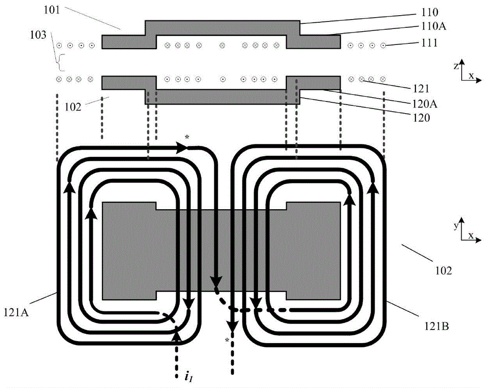
[0066] figure 2 It is a schematic structural diagram of the first embodiment of the non-contact transformer of the present invention, as figure 2 As shown, in the first embodiment, the structures of the primary side magnetic core 110 and the secondary side magnetic core 120 are two side columns (the primary side magnetic core side column 110A and the secondary side magnetic core side column 120A) and the bottom expands outward along the side The edge extension type, and the primary winding 111 is formed by two parts of the windings wound on the two magnetic core side columns in series in the forward direction or in parallel on different sides; the secondary winding includes the secondary main winding 121 ( figure 2 not shown in the lower figure) and an additional auxiliary winding 122. Thus forming the non-contact transformer with additional auxiliary winding of the present invention. Among them, the primary winding, secondary main winding, and auxiliary winding can be wound...

Embodiment 2

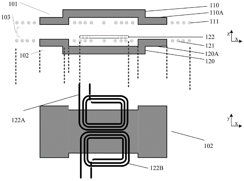
[0071] image 3 It is a schematic structural diagram of the second embodiment of the non-contact transformer of the present invention, as image 3As shown, in the second embodiment, the structure of the primary side magnetic core 110 is an edge expansion type in which the bottom of the two side columns (primary side magnetic core side column 110A) expands outward along the side, and the basic shape of the secondary side magnetic core is a cross structure, in which in the x direction, the edge-expanded characteristic structure in which the bottom of the two-side columns (secondary side magnetic core side column 120A) expands outward along the side is adopted, and the magnetic core part (120B) of the secondary side in the y-direction can also adopt edge expansion type structure. The entire magnetic core can be made of a whole magnetic core or multiple magnetic cores spliced ​​together, that is, an array-type magnetic core structure is adopted, and the x-direction magnetic cores...

Embodiment 3

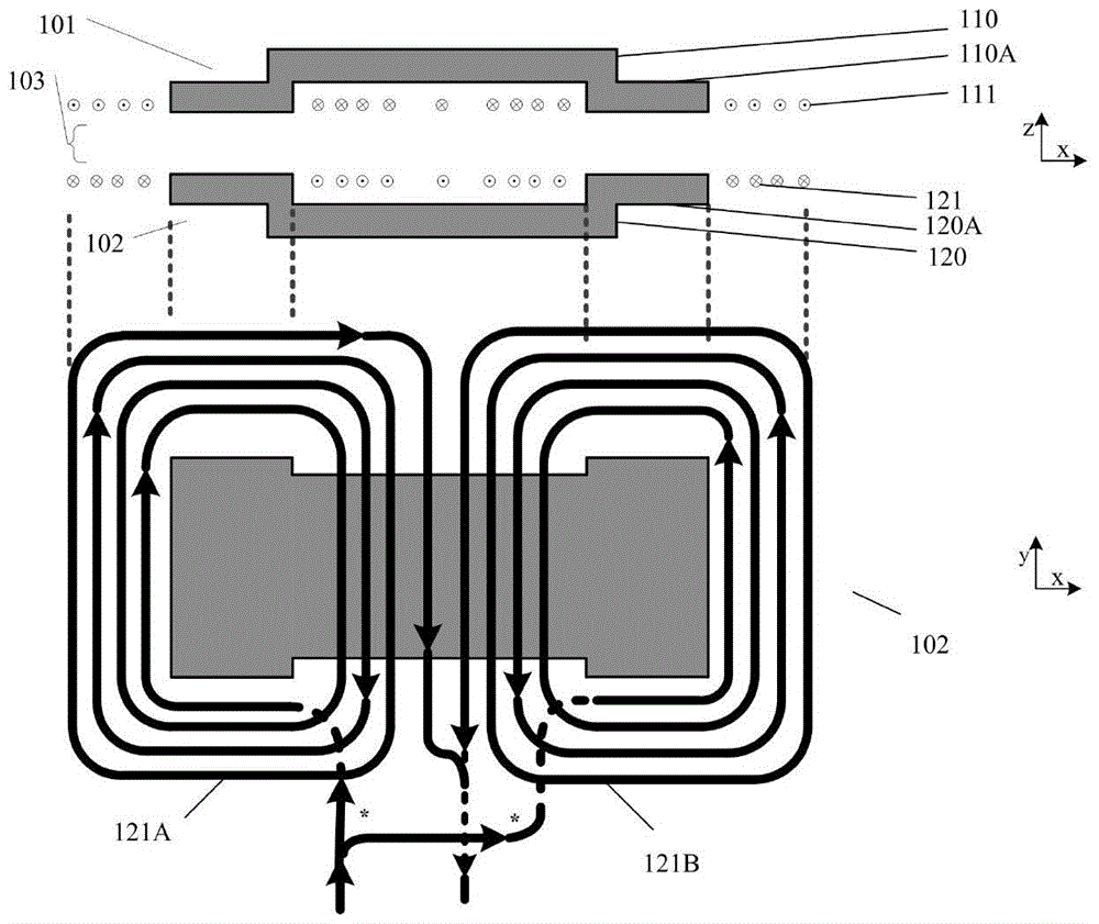
[0075] Figure 4 It is a structural schematic diagram of the third embodiment of the non-contact transformer of the present invention, as Figure 4 As shown, in the fourth embodiment, the structures of the primary side magnetic core 110 and the secondary side magnetic core 120 are two side columns (the primary side magnetic core side column 110A and the secondary side magnetic core side column 120A) and the bottom expands outward along the side The edge extension type, and the primary winding 111 is formed by two parts of the windings wound on the two magnetic core side columns in series in the forward direction or in parallel on different sides; the secondary winding includes the secondary main winding 121 ( Figure 4 not shown in the lower figure) and an additional auxiliary winding 322. Thus forming the non-contact transformer with additional auxiliary winding of the present invention.

[0076] The auxiliary winding 322 is divided into two sections. The two sections of wi...


PUM


Abstract

The invention discloses a contactless transformer, which comprises a primary-side magnetic core, a primary-side winding, a secondary-side magnetic core and a secondary-side winding, wherein the secondary-side winding of the contactless transformer comprises a main secondary-side winding and an auxiliary winding; the auxiliary winding is of a two-section type or a multi-section type; each section of the auxiliary winding is overlapped, partially overlapped or not overlapped with the main secondary-side winding. According to the contactless transformer, each section of the auxiliary winding is distributed in different areas of the secondary-side magnetic core of the contactless transformer to form one, two or more auxiliary winding units, and the auxiliary winding units with optimal magnetic flux coupling effects are automatically switched under the conditions of dislocation in different directions and different degrees, so that the condition of no power transmission at a sending blind spot is further avoided by the combined output of each auxiliary winding unit and the main secondary-side winding, the power transmission of the main secondary-side winding is effectively compensated, the dislocation sensitivity of output characteristics of the contactless transformer is reduced, and the power transmission capability of the contactless transformer is improved.

Description

technical field [0001] The invention relates to a non-contact power supply technology, in particular to a non-contact transformer in which a secondary winding is supplemented with two or more auxiliary windings and combined with a secondary primary winding. Background technique [0002] Non-contact power supply uses magnetic field coupling to realize "wireless power supply", that is, a non-contact transformer with completely separated primary and secondary sides is used to transmit electric energy through high-frequency magnetic field coupling, so that the primary side (power supply side) and secondary side (power consumption side) side) no physical connection. Compared with the traditional contact power supply, non-contact power supply is convenient and safe to use, without sparks and electric shock hazards, without dust accumulation and contact loss, without mechanical wear and corresponding maintenance problems, and can adapt to a variety of severe weather and environment...

Claims


Application Information

Patent Timeline
Patent Type & Authority Patents(China)
IPC IPC(8): H01F27/28H01F27/30H01F27/24H01F27/36H01F30/06
Inventor 陈乾宏柯光洁徐立刚任小永
Owner NANJING UNIV OF AERONAUTICS & ASTRONAUTICS
Why Eureka
Try Eureka