
Wet etching equipment

A technology of wet etching and equipment, which is applied in the field of microelectronic processing equipment, can solve the problems of reducing equipment utilization rate, affecting product quality, and environmental pollution inside the machine, so as to reduce production costs and improve equipment utilization rate. Effect

Active Publication Date: 2015-06-03
BOE TECH GRP CO LTD
View PDF9 Cites 15 Cited by
  • Summary
  • Abstract
  • Description
  • Claims
  • Application Information

AI Technical Summary

Problems solved by technology

After a long time, it can cover the entrance and exit of the entire etching chamber. If it is not cleaned in time, it will cause pollution to the internal environment of the machine, and even cause scratches on the substrate, seriously affecting product quality
However, frequent cleaning will take up a lot of up time of the equipment and reduce the utilization rate of the equipment

Method used


Image

  • Wet etching equipment
  • Wet etching equipment
  • Wet etching equipment

Examples


no. 1 example

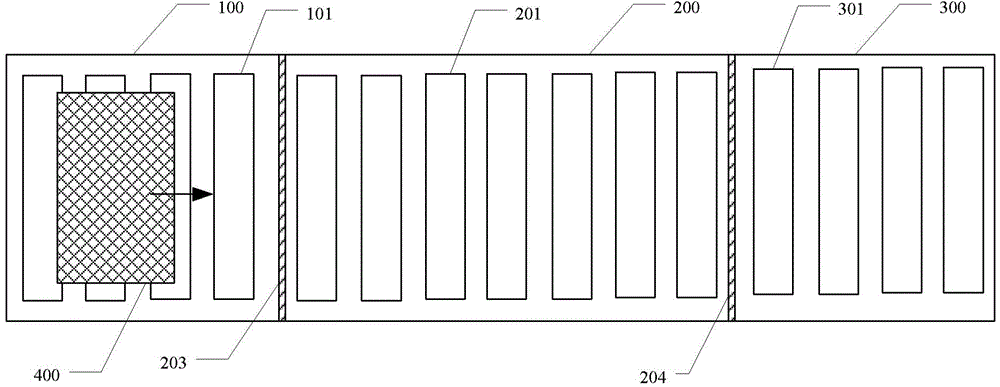
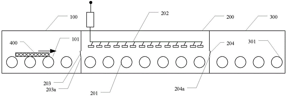
[0045] In an exemplary embodiment of the present invention, a wet etching apparatus is provided. Figure 4A It is a schematic diagram of wet etching equipment according to the first embodiment of the present invention. Figure 4B for Figure 4AA schematic diagram of the position of the front buffer chamber close to the etching chamber in the wet etching equipment shown. like Figure 4A and Figure 4B As shown, the wet etching equipment of this embodiment includes: a front buffer chamber 100 , an etching chamber 200 , a rear buffer chamber 300 and a decrystallization device 500 . The decrystallization device 500 includes: a front spray pipe 501 installed in the front buffer chamber 100 near the etching chamber 200; a rear spray pipe 502 installed in the rear buffer chamber 300 near the etching chamber 200; and Liquid supply pipeline 503. The front spray pipe 501 and the rear spray pipe 502 are supplied with liquid by a liquid supply pipeline 503 for cleaning the etching li...

no. 3 example

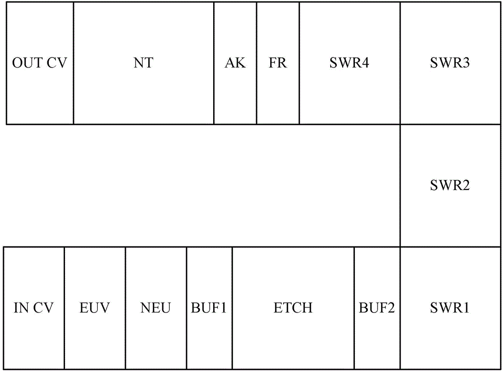
[0070] In another embodiment of the present invention, another wet etching device is also provided. The difference between the wet etching equipment of this embodiment and the second embodiment is that: a pipeline is drawn from the waste water discharge pipeline of the first water washing unit SWR1 of the wet etching equipment to supply water to the water tank. The washing flow rate of the first water washing unit SWR1 is relatively large, which can fully meet the water volume of the decrystallization device to remove oxalic acid crystals, and the excess water volume can be discharged from the top of the water tank.

[0071] Other working principles of the wet etching equipment in this embodiment are the same as those in the second embodiment, and will not be repeated here.

[0072] Under normal circumstances, the waste water of the first water washing unit SWR1 is directly discharged. The advantages of this embodiment are: the effect of removing crystals is good, the waste w...


PUM


Abstract

The invention provides wet etching equipment. The wet etching equipment has a function of removing etching liquid crystal outside an etching chamber, and comprises the etching chamber and a spray pipe, wherein a film to be etched is etched through etching liquor inside the etching chamber; an etching chamber inlet is formed in the front end of the etching chamber; an etching chamber outlet is formed in the rear end of the etching chamber; the spray pipe is arranged below the etching chamber inlet and / or the etching chamber outlet, and can be towards to the upper part to spray liquid, so as to clean etching liquid crystal formed at the etching chamber inlet and / or the etching chamber outlet. The wet etching equipment adopts the spray pipe to spray the etching chamber inlet and the etching chamber outlet, can effectively remove a large amount of etching liquid crystal produced at the etching chamber inlet and the etching chamber outlet, improves the equipment operation ratio, cleanness and product quality, and solves a major problem in a TFT base substrate manufacture technology.

Description

technical field [0001] The invention relates to the technical field of microelectronic processing equipment, in particular to a wet etching equipment. Background technique [0002] At present, in the Flat Panel Display (FPD) technology, the Liquid Crystal Display (LCD) has gradually replaced the Cathode Ray Tube (Cathode Ray Tube, referred to as CRT), becoming the mainstream display. Among various types of LCD, Thin Film Transistor-Liquid Crystal Display (TFT-LCD for short) has the advantages of excellent performance and suitable for large-scale automatic production, and has become the mainstream LCD product. [0003] In the TFT-LCD manufacturing process, ITO (Indium Tin Oxide, Indium Tin Oxide) is widely used to make transparent display electrodes due to its excellent characteristics. In the process of making ITO transparent display electrodes, the ITO film is first formed by magnetron sputtering (sputter), then the photoresist pattern is formed by photolithography, and f...

Claims


Application Information

Patent Timeline
Patent Type & Authority Applications(China)
IPC IPC(8): H01L21/67
CPCH01L21/6708H01L21/67173H01L21/6776H01L21/30604H01L21/67023
Inventor 薛大鹏
Owner BOE TECH GRP CO LTD
Learn More