
Longitudinal local beam-expanding triple frequency laser terminal optical system

An optical system and triple frequency technology, applied in optics, lasers, nonlinear optics, etc., can solve problems such as increased cost and system complexity, mismatched optical component loads, increased device operating costs, etc., to save installation space, The effect of reducing system complexity and reducing implementation costs

Inactive Publication Date: 2015-06-03
LASER FUSION RES CENT CHINA ACAD OF ENG PHYSICS
View PDF7 Cites 2 Cited by
  • Summary
  • Abstract
  • Description
  • Claims
  • Application Information

AI Technical Summary

Problems solved by technology

In order to suppress the laser plasma instability (Laser Plasam Instablity, LPI) problem during the shooting process, it is necessary to convert the frequency of the neodymium glass near-infrared laser into a triple-frequency ultraviolet laser with a shorter wavelength. A serious engineering problem was exposed. The optical components in the ultraviolet section of the triple frequency laser terminal optical system (mainly completing the frequency conversion and beam focusing functions) were severely damaged, which increased the operating cost of the device and reduced the operating efficiency of the device.
In fact, the operation of the optical components of the base frequency band of the device is much better. It can be seen that there is a problem that the load of the optical components of the base frequency band and the triple frequency band does not match. In order to solve this problem, the simplest and most effective way is to use the triple frequency laser The terminal optical system expands the beam to reduce the average flux of the three-frequency laser, but the beam expansion often brings a significant increase in cost and system complexity, and the implementation is very difficult. This patent is proposed to solve this problem

Method used


Image

  • Longitudinal local beam-expanding triple frequency laser terminal optical system
  • Longitudinal local beam-expanding triple frequency laser terminal optical system
  • Longitudinal local beam-expanding triple frequency laser terminal optical system

Examples


Embodiment Construction

[0020] The present invention will be further described in detail below in conjunction with the accompanying drawings, so that those skilled in the art can implement it with reference to the description.

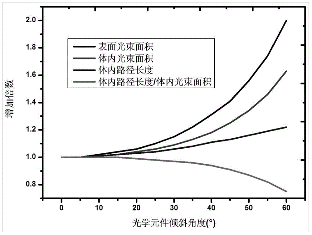
[0021] like figure 1 As shown, as the tilt angle of the optical element increases, the surface beam area, in vivo beam area, and in vivo path length all increase, while the ratio of in vivo path length to in vivo beam area decreases. For the same input laser energy, this means that the laser flux on the surface of the optical element is reduced, the laser intensity in the body is reduced, the thickness of the laser medium is increased, and the laser intensity in the body is multiplied by the thickness of the laser medium. Linear effects are mitigated. Taking the Brewster's angle placement of optical components as an example, the refractive index is 1.5, the inclination angle is 56.3°, the surface laser flux is reduced by 1.8 times, the laser intensity in the body is reduced ...


PUM


Abstract

The invention relates to the field of high power laser and particularly relates to a longitudinal local beam-expanding triple frequency laser terminal optical system. The system comprises a double frequency crystal, a first cylindrical focusing lens, a triple frequency crystal and a second cylindrical focusing lens which are sequentially arranged in the transmission direction of an incident laser beam, wherein the triple frequency crystal and the second cylindrical focusing lens are obliquely arranged, the triple frequency crystal inclines along a vertical rotary shaft of the triple frequency crystal, the second cylindrical focusing lens inclines along a horizontal rotary shaft of the second cylindrical focusing lens, and the vertical rotary shaft of the triple frequency crystal and the horizontal rotary shaft of the second cylindrical focusing lens are mutually orthogonal. According to the longitudinal local beam-expanding triple frequency laser terminal optical system, local beam expanding can be realized to reduce the mean flux of the triple frequency laser, the severe ultraviolet damage problem is alleviate, and meanwhile, the implementation cost and the system complexity are reduced.

Description

technical field [0001] The invention relates to the field of high-power lasers, in particular to a longitudinal local beam-expanding triple frequency laser terminal optical system. Background technique [0002] Inertial Confinement Fusion (ICF) is one of the effective ways to realize controllable thermonuclear fusion, and all major countries in the world are actively carrying out related research. At present, there are many large-scale laser devices that have been built or are being built for ICF research, such as the NIF device in the United States, the LMJ device in France, and the Shenguang series devices in China. Because the neodymium glass laser has the characteristics of high output power and easy control, most devices are designed based on the neodymium glass laser. In order to suppress the laser plasma instability (Laser Plasam Instablity, LPI) problem during the shooting process, it is necessary to convert the frequency of the neodymium glass near-infrared laser i...

Claims


Application Information

Patent Timeline
IPC IPC(8): H01S3/109G02F1/35G02F1/37
Inventor 张小民李富全魏晓峰韩伟王芳向勇周丽丹王礼权敬域堃冯斌李明中朱启华郑奎兴粟敬钦胡东霞
Owner LASER FUSION RES CENT CHINA ACAD OF ENG PHYSICS
Learn More