Power conversion circuit
A power conversion circuit and circuit technology, applied in the direction of high-efficiency power electronic conversion, electronic commutation motor control, electronic commutator, etc., can solve the problems of energy consumption, reduction of effective output of motors, waste of energy, etc., to achieve low negative power, High effective power and reduced waste
- Summary
- Abstract
- Description
- Claims
- Application Information
AI Technical Summary
Problems solved by technology
Method used
Image
Examples
no. 1 approach
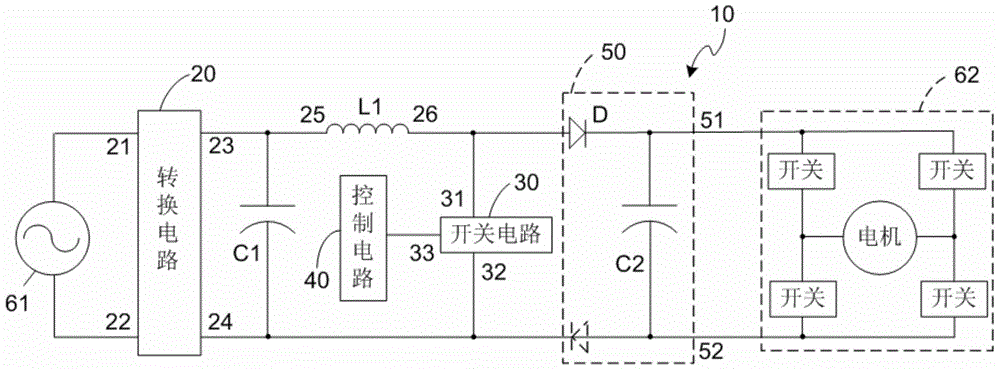
[0020] Please combine image 3 , the conversion circuit 20 in the power conversion circuit 10 of the first embodiment of the present invention may be a half-bridge diode rectifier bridge (not shown in the figure). The switch circuit 30 can be a BJT or MOSFET transistor, its collector and emitter (or drain and source) are the above-mentioned first and second controlled terminals 31 and 32, and its base (or gate) is the above-mentioned control terminal 33. The first controlled terminal 31 is connected to the first DC terminal 23 through the first inductor L1 , and the second controlled terminal 32 is connected to the second DC terminal 24 . The control circuit 40 may include a signal generator such as a PWM signal generator or a single chip microcomputer.
[0021] The energy storage circuit 50 includes a second capacitor C2 and a diode D. The second capacitor C2 is connected between the first and second output terminals 51 and 52 . The diode D is connected between the first ...
no. 2 approach
[0031] Please combine Figure 5 The difference between the power conversion circuit 10b of the second embodiment of the present invention and the power conversion circuit 10 of the above-mentioned first embodiment lies in the energy storage circuit 50b. The conversion circuit 50b of the second embodiment further includes a third capacitor C3 and a second inductor L2 in addition to the diode D and the second capacitor C2 in the first embodiment. The third capacitor C3 is connected between the second connection terminal 26 and the diode D, and the second inductor L2 is connected between the second DC terminal 24 and the end of the third capacitor C3 close to the first output terminal 51 (that is, the third capacitor C3 and the diode D between one end of the connection).
[0032] Please reunite Figure 6 , in the working process, as mentioned above, when the brushless DC motor rotates to generate a counter electromotive force and the voltage of the AC power supply 61 gradually ...
PUM
 Abstract
Description
Claims
Application Information
 - R&D
- Intellectual Property
- Life Sciences
- Materials
- Tech Scout
- Unparalleled Data Quality
- Higher Quality Content
- 60% Fewer Hallucinations
Browse by: Latest US Patents, China's latest patents, Technical Efficacy Thesaurus, Application Domain, Technology Topic, Popular Technical Reports.
© 2025 PatSnap. All rights reserved.Legal|Privacy policy|Modern Slavery Act Transparency Statement|Sitemap|About US| Contact US: help@patsnap.com


