System and method for synergistically removing dust and condensable particles in flue gas

A particle and flue gas technology, which is applied in the system field of collaborative removal of dust and condensable particulate matter in flue gas, can solve the problems of weak ability to remove condensable particulate matter and does not involve the removal of condensable particulate matter

Active Publication Date: 2015-06-17
高境 +2
View PDF9 Cites 15 Cited by
  • Summary
  • Abstract
  • Description
  • Claims
  • Application Information

AI Technical Summary

Problems solved by technology

Usually, the proportion of PM1 in PM2.5 in coal-fired dust is 17-19%. Although this method has a removal efficiency of about 80% for PM2.5 dust, most of PM1 dust is still not removed, and condensable particles also It is discharged into the air; and this method does not involve the removal of condensable particles, and the ability to remove condensable particles by this method is also weak

Method used


Image

  • System and method for synergistically removing dust and condensable particles in flue gas
  • System and method for synergistically removing dust and condensable particles in flue gas
  • System and method for synergistically removing dust and condensable particles in flue gas

Examples


Embodiment 1

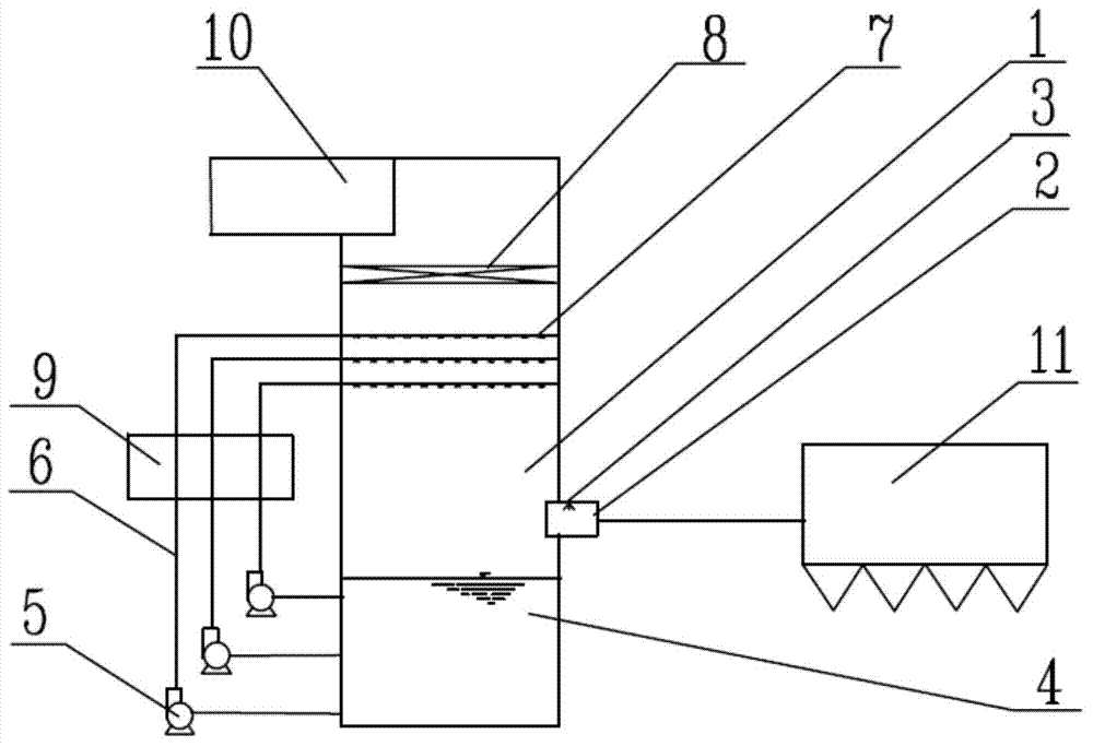
[0124] Such as figure 1 The sprinkler system shown, the process of using this system to cooperatively remove dust and condensable particulate matter in the flue gas is specifically: a coal-fired boiler, the flue gas temperature after the air preheater is 130 degrees Celsius, first passes through the micro-pressure Reverse blowing bag filter dust removal, after testing, the original flue gas dust concentration is reduced to 15mg / Nm 3 , in addition, there is 50mg / Nm in the flue gas 3 SO 3 The flue gas enters the spray tower again. At the entrance of the spray tower, a water spray cooling device is provided. The flue gas is cooled and humidified by evaporating the spray water. Become saturated wet flue gas, usually the temperature of the flue gas can drop to about 50°C. Studies have shown that SO 3 It is gaseous at 120°C, and condenses into H after humidification and cooling 2 SO 4 The droplets are quickly adsorbed on the surface of the dust particles, which improves the mo...

Embodiment 2

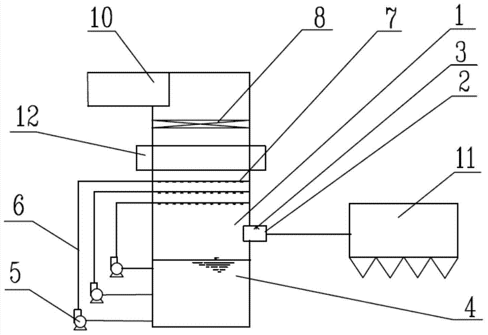
[0127] Such as figure 2 The sprinkler system shown, the process of using this system to collaboratively remove dust and condensable particles in the flue gas is as follows: a coal-fired boiler, the flue gas temperature after the air preheater is 130 ℃, first passes through the micro pressure Reverse blow bag filter dust removal, the dust concentration of the original flue gas is reduced to 15mg / Nm 3 , in addition, there is 50mg / Nm in the flue gas 3 SO 3 The flue gas enters into the spray tower of the present invention again, and at the entrance of the spray tower, a water spray cooling device is provided, and the flue gas is cooled and humidified by evaporating the spray water, and the flue gas becomes saturated wet flue gas, usually the flue gas temperature It can be reduced to about 50 degrees Celsius. The temperature of the slurry in the slurry tank is considered to be the same as that of the saturated wet flue gas, which is also 50°C, and the temperature of the humidif...

Embodiment 3

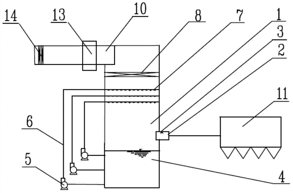
[0131] It is the same as the spraying system described in Example 1, the difference is that no heat exchanger is installed on the slurry pipe, a second finned heat exchanger is added in the clean flue, cooling water flows through the pipe, and humidified flue gas is outside the pipe, such as image 3 As shown, the humidified flue gas enters the clean flue, and after passing through the heat exchanger in the clean flue, the humidified flue gas cools down by 1°C, and the residual liquid droplets in the clean flue gas can continue to condense and grow. A clean flue demister is installed at the end of the clean flue to remove the grown droplets, and the dust concentration is further reduced to 3mg / Nm 3 , SO 3 Concentration down to 6mg / Nm 3 .


PUM

PropertyMeasurementUnit
particle diameteraaaaaaaaaa

Abstract

The invention provides a system and a method for synergistically removing dust and condensable particles in flue gas. The system comprises a dust remover, a spraying tower inlet, a water-spraying cooling device, a clean flue, a spraying layer, a demister, a slurry pond, a slurry pipe, a circulating pump and a heat exchanger, wherein the heat exchanger is arranged on the slurry pipe. The invention further provides a system which comprises a first heat exchanger, and the first heat exchanger is arranged between the demister and the spraying layer. The invention further provides a system which comprises a second heat exchanger and a first demister arranged in the clean flue, and the second heat exchanger is arranged in front of the first demister. By arranging the heat exchanger in a spraying tower, saturated wet flue gas or nearly saturated wet flue gas formed by spraying is cooled, oversaturated wet flue gas is formed, the dust and the condensable particles in the flue gas are condensed and absorb moisture to form liquid droplets, and the liquid droplets grow up, so that the removal rate of the dust and the condensable particles in the flue gas is increased.

Description

technical field [0001] The invention relates to the technical field of flue gas treatment, in particular to a system and method for cooperatively removing dust and condensable particulate matter in flue gas. Background technique [0002] In the coal-fired flue gas produced by electric power, metallurgy, mining, chemical industry, cement and other industries and the flue gas obtained from the incineration of fuels such as oil, natural gas, and garbage, except solid particulate matter and gaseous SO 2 , NO x In addition to conventional pollutants such as flue gas, there is also a class of substances that are gaseous in the state of flue gas and condense into liquid or solid within a few seconds after leaving the flue when the ambient temperature drops. Such substances include SO 3 , ammonium salts, nitrates, sulfites, volatile organic compounds and heavy metal substances, etc., are collectively referred to as condensable particulate matter. [0003] Taking the power industry...

Claims


Application Information

Patent Timeline
Patent Type & Authority Applications(China)
IPC IPC(8): B01D50/00B01D53/80B01D53/50
Inventor 李艳萍高境
Owner 高境
Why Eureka
Try Eureka