Screw drilling tool stator prepared from blend of PTFE and FEP, and fluorine-containing material applied to stator

A technology of screw drilling tools and PTFE, which is applied in the field of screw drilling tool stators and fluorine-containing materials, can solve the problems that affect the drilling efficiency and development progress, the technical difficulty of tubular shell processing, and the complicated molding process, etc., and achieve low friction coefficient , good wear resistance, low friction coefficient effect

Active Publication Date: 2015-06-17
ZHEJIANG GREEN NEW MATERIALS
View PDF6 Cites 1 Cited by
  • Summary
  • Abstract
  • Description
  • Claims
  • Application Information

AI Technical Summary

Problems solved by technology

[0003] Since the inner wall of the tubular casing of the stator in the prior art is provided with concave thread grooves, the processing technology of the tubular casing is difficult, the molding process is complicated, and more processing residues are generated, which greatly increases the processing cost
In addition, the rubber bushing is injected on the inner wall of the housing by high pressure, and the molding process is also very complicated, with high processing costs and low labor efficiency
In the prior art, the rubber bushing materials of screw drilling tools are generally NBR and HNBR. Among them, the limit temperature (static) of HNBR is 176°C, but the long-term temperature of high-temperature wells is close to 170°C. According to the working characteristics of screw drilling tools, The temperature is easy to concentrate on the part where the rubber bush and the rotor are in contact, and the dynamic heat generated by mutual extrusion and torsion between the stator and the rotor
When the temperature is high and concentrated in the above area for a long time, it will cause the aging of the rubber bushing, which will cause rubber damage
Therefore, the service life of screw drilling tools in high-temperature wells is generally more than 100 hours, the service life is short, and the maintenance requirements are high, which affects the efficiency and progress of drilling work and increases drilling costs.

Method used


Image

  • Screw drilling tool stator prepared from blend of PTFE and FEP, and fluorine-containing material applied to stator
  • Screw drilling tool stator prepared from blend of PTFE and FEP, and fluorine-containing material applied to stator
  • Screw drilling tool stator prepared from blend of PTFE and FEP, and fluorine-containing material applied to stator

Examples


Embodiment 1

[0052] The components of this embodiment (in parts by weight) consist of: 100 parts of PTFE and FEP blend, PTFE accounts for 90%, and FEP accounts for 10%; 10 parts of additives, with a diameter of 15 μm and an aspect ratio of 150: 1 carbon fiber and copper powder with a particle size of less than 0.3 μm are mixed at a weight ratio of 2:1. Carbon fibers were treated with a surface modifier prepared by a rare earth modifier with a rare earth concentration of 0.1% and a coupling agent of 2%, soaked at room temperature for 3 hours, and then baked at 80°C for 3 hours.

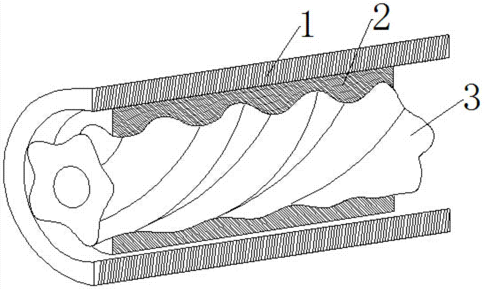
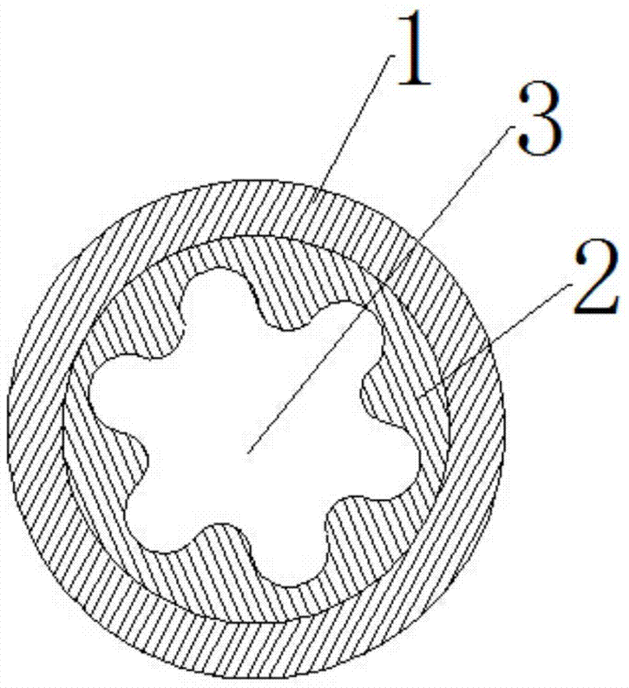
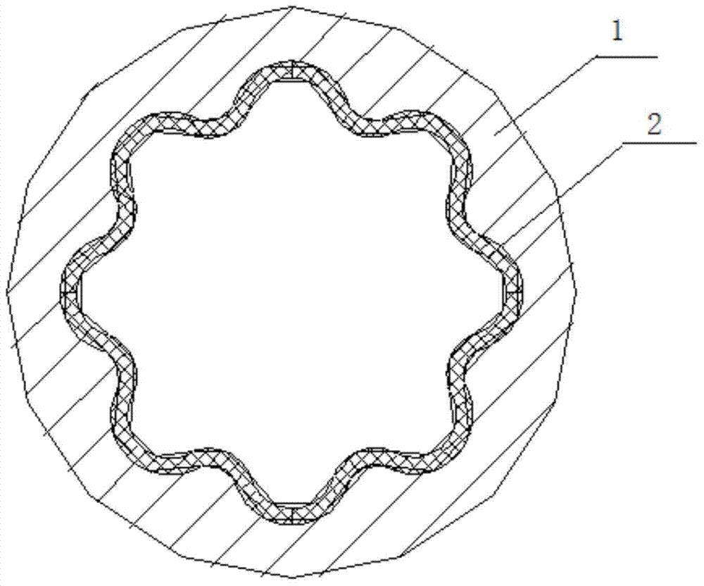
[0053] During production, FEP, PTFE and additives are mixed uniformly by a high-speed kneader, then smelted, extruded and granulated into powder, and then formed by extrusion, injection molding or die casting to obtain one of the application structures such as Figure 1-3 shown.

Embodiment 2

[0055] The components of this embodiment (in parts by weight) consist of: 100 parts of PTFE and FEP blend, PTFE accounts for 80%, and FEP accounts for 20%; 10 parts of additives, with a diameter of 15 μm and an aspect ratio of 150: 1 glass fiber and copper powder and iron powder with a particle size of less than 0.3 μm are mixed at a weight ratio of 2:1. The glass fiber is treated with a surface modifier prepared by a rare earth modifier with a rare earth concentration of 0.2% and a coupling agent of 3%, soaked at room temperature for 2 hours, and then baked at 90°C for 4 hours.

[0056] During production, FEP, PTFE and additives are mixed uniformly by a high-speed kneader, then smelted, extruded and granulated into powder, and then formed by extrusion, injection molding or die casting to obtain one of the application structures such as Figure 1-3 shown.

Embodiment 3

[0058] The components of this embodiment (in parts by weight) consist of: 100 parts of PTFE and FEP blend, PTFE accounts for 75%, and FEP accounts for 25%; 10 parts of additives, with a diameter of 15 μm and an aspect ratio of 150: 1 boron fiber and copper powder and tungsten powder with a particle size of less than 0.3 μm are mixed at a weight ratio of 2:1. The boron fibers were treated with a surface modifier prepared by a rare earth modifier with a rare earth concentration of 0.3% and a coupling agent of 4%, soaked at room temperature for 2 hours, and then baked at 100°C for 4 hours.

[0059] During production, FEP, PTFE and additives are mixed uniformly by a high-speed kneader, then smelted, extruded and granulated into powder, and then formed by extrusion, injection molding or die casting to obtain one of the application structures such as Figure 1-3 shown.


PUM

PropertyMeasurementUnit
densityaaaaaaaaaa
densityaaaaaaaaaa
diameteraaaaaaaaaa

Abstract

The invention relates to a screw drilling tool stator prepared from a blend of PTFE and FEP. The stator mainly comprises, from exterior to interior, an outer metal tube and a polymer layer, wherein the polymer layer is prepared from the blend of PTFE and FEP. In virtue of the advantages of good wear resistance, operating temperature range and weatherability, low friction coefficient and the like of the blend of PTFE and FEP, the performance of a drilling tool is effectively improved in the aspects of operating temperature range, wear rate and the like of the screw drilling tool stator, so the service life of the screw drilling tool stator is greatly prolonged, productive maintenance cost is reduced, and well drilling efficiency is improved.

Description

technical field [0001] The invention relates to a stator of a screw drilling tool, in particular to a stator of a screw drilling tool made of a blend of PTFE and FEP and a fluorine-containing material. Background technique [0002] The screw drilling tool is a volumetric downhole power drilling tool that uses drilling fluid as power and converts fluid pressure energy into mechanical energy. It generally consists of a bypass valve, a screw motor, a universal joint, a bearing and a drive shaft, and its core is a screw motor. The screw motor is composed of a stator and a rotor. In the existing technology, such as figure 1 As shown, the stator includes a tubular housing 100 and a rubber bushing 201 that is closely connected to the inner wall of the housing. The inner wall of the tubular housing 100 is provided with a concave thread groove, and the thread groove is provided with At least 3 and arranged side by side on the inner wall 100 of the housing. The helical directions o...

Claims


Application Information

Patent Timeline
Patent Type & Authority Applications(China)
IPC IPC(8): F03C2/08C08L27/18C08L27/20C08L77/10C08K9/00C08K7/06C08K7/14C08K3/08
CPCC08K2201/014C08L27/18C08L2201/08C08L2205/025C08L2205/03C08L2205/16F03C2/08C08K9/02C08K7/06C08K2003/085C08K7/14C08K2003/0856C08K2003/0887C08L77/10C08K3/08C08L67/00C08L77/00C08L79/08C08K2003/0881C08K2003/0812
Inventor 徐洪徐诚吾良福景亚宾
Owner ZHEJIANG GREEN NEW MATERIALS
Why Eureka
Try Eureka