Test method for welding spot quality of resistance spot welding based on dynamic resistance curve
A technology of dynamic resistance curve and dynamic resistance, which is applied in the field of on-line quality inspection at the production site, can solve the problems of inability to guarantee the quality and reliability of untested products, low efficiency, and increased production costs, and achieves simple evaluation methods, low misjudgment rates, easy-to-achieve effects
- Summary
- Abstract
- Description
- Claims
- Application Information
AI Technical Summary
Problems solved by technology
Method used
Image
Examples
Embodiment 1
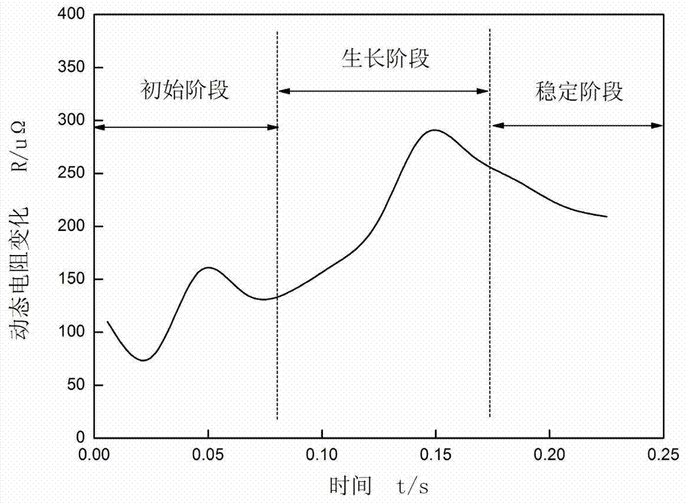
[0051] Embodiment 1: First, to make standard dynamic resistance curves of different materials with different thicknesses, the method is as follows:
[0052] (1) Select two welded samples of low-carbon steel sheet structure with a thickness of 1mm for lap joint. The main welding process parameters used are: the welding current is 5500A, the welding current duration is 0.28s, and the electrode pressure is 0.15MPa;
[0053] (1) Real-time acquisition of the welding current signal and the electrode voltage signal of the resistance spot welding process in the secondary circuit of the resistance spot welding machine during the welding process;
[0054] (2) draw out the signal waveform of welding current and electrode voltage changing with time in the computer system;
[0055] (3) Use the computer system to divide the electrode voltage signal and the welding current signal waveform, and then draw the standard dynamic resistance curve of the solder joint formation process, such as fi...
Embodiment 2
[0057] Embodiment 2: Quality detection of resistance spot welding solder joints on low carbon steel plates with a thickness of 1 mm
[0058] The workpiece to be welded is a lap joint of two low-carbon steel sheet structures with a thickness of 1mm. The main welding process parameters used are: welding current 2000A, welding current duration 0.28s, electrode pressure 0.15MPa.
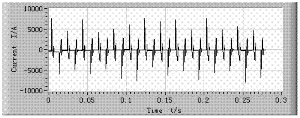
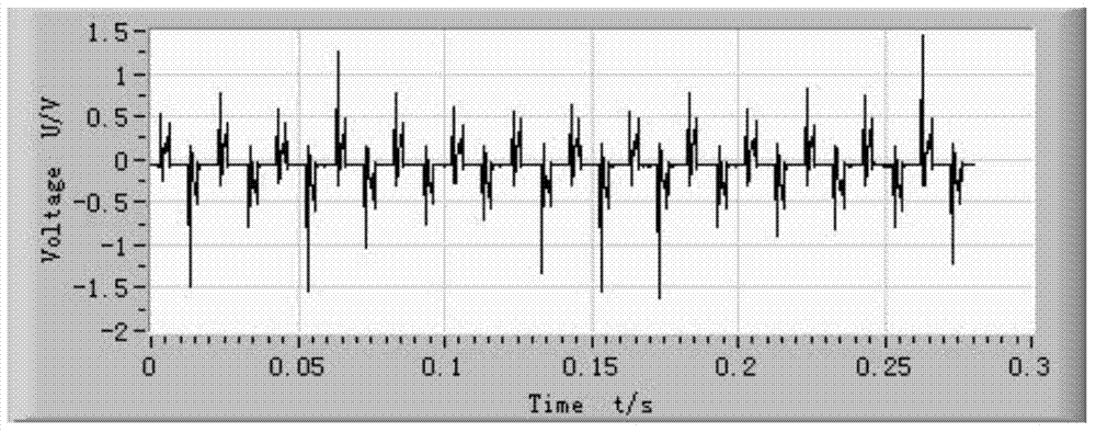
[0059] During welding, the welding current signal and electrode voltage signal of the resistance spot welding process are collected in real time, and the signal waveform diagram is drawn by the analysis software, as shown in figure 2 with image 3 shown. Then the dynamic resistance change curve of the solder joint formation process is obtained, such as Figure 4 shown.
[0060] Will Figure 4 Dynamic resistance curve vs. figure 1 Compared with the standard dynamic resistance curve shown, it can be seen that Figure 4 The dynamic resistance curve shown has only an initial phase of unstable nucleati...
Embodiment 3
[0062] Embodiment 3: Quality detection of resistance spot welding solder joints of low carbon steel materials with a thickness of 1 mm
[0063] The workpiece to be welded is the overlapping joint of two low-carbon steel sheet structures with a thickness of 1 mm. The main welding process parameters used are: welding current is 3500A, welding current duration is 0.28s, electrode pressure is 0.15MPa.
[0064] During welding, the welding current signal and electrode voltage signal of the resistance spot welding process are collected in real time, and the signal waveform diagram is drawn by the analysis software, as shown in Image 6 with Figure 7 shown. Then the dynamic resistance change curve of the solder joint formation process is obtained, such as Figure 8 shown.
[0065] Will Figure 8 Dynamic resistance curve vs. figure 1 Compared with the standard dynamic resistance curve shown, it can be seen that Figure 8 The dynamic resistance curve shown consists only of the i...
PUM
| Property | Measurement | Unit |
|---|---|---|
| Thickness | aaaaa | aaaaa |
Abstract
Description
Claims
Application Information
 - R&D
- Intellectual Property
- Life Sciences
- Materials
- Tech Scout
- Unparalleled Data Quality
- Higher Quality Content
- 60% Fewer Hallucinations
Browse by: Latest US Patents, China's latest patents, Technical Efficacy Thesaurus, Application Domain, Technology Topic, Popular Technical Reports.
© 2025 PatSnap. All rights reserved.Legal|Privacy policy|Modern Slavery Act Transparency Statement|Sitemap|About US| Contact US: help@patsnap.com


