Waste processor

A garbage processor and garbage technology, applied in grain processing, air heaters, fluid heaters, etc., can solve the problems of regular cleaning, odor generation, environmental hazards, etc., to reduce maintenance costs, reduce energy consumption, and improve the effect. Effect

Inactive Publication Date: 2015-07-01
钱海荣
View PDF9 Cites 15 Cited by
  • Summary
  • Abstract
  • Description
  • Claims
  • Application Information

AI Technical Summary

Problems solved by technology

[0002] In industrial production, with the production operations, a large amount of industrial waste will be produced. These industrial wastes will produce peculiar smell, breed bacteria, and usually contain heavy metals and some harmful substances. If they are not handled correctly, they will cause great harm to the environment. harm
In daily life, hotels, food processing factories and other occasions will produce a large amount of food waste and domestic waste, which are easy to deteriorate and rot, and will pollute the environment if not handled properly
For such a situation, some garbage disposal equipments have been designed and developed, but most of these garbage disposal equipments are complex in structure and bulky, and residues are easy to accumulate inside the garbage disposal equipment, which cannot be removed in time during the crushing work, and will be damaged after long-term use. Cause the machine to be stuck, especially the mesh cover used in solid-liquid separation, which is easy to block and needs to be cleaned regularly, which is time-consuming and labor-intensive; and the effect of solid-liquid separation is not good
In order to prevent the oil from solidifying in the traditional oil-water separation tank, electric heating wires are used to heat the liquid in the oil-water separation tank, which consumes a lot of power

Method used


Image

  • Waste processor
  • Waste processor
  • Waste processor

Examples


Embodiment Construction

[0024] The preferred embodiments of the present invention will be described in detail below in conjunction with the accompanying drawings, so that the advantages and features of the present invention can be more easily understood by those skilled in the art, so as to define the protection scope of the present invention more clearly.

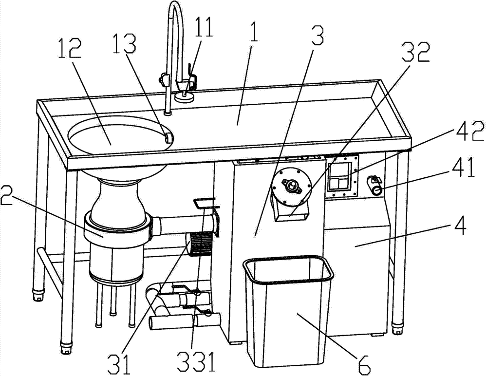
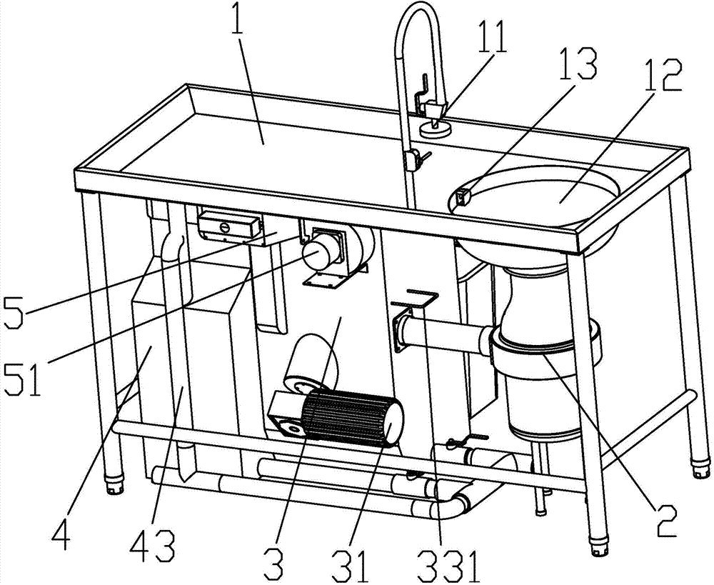
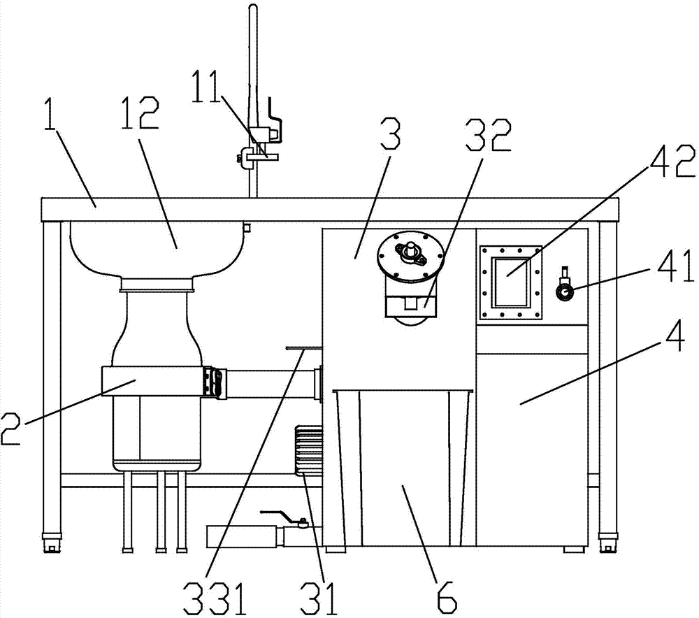
[0025] see Figure 1 to Figure 10 , the embodiment of the present invention includes:

[0026] A garbage processor, comprising: a workbench 1 and a garbage crusher 2 arranged under the workbench 1, a solid-liquid separator 3, an oil-water separation box 4, a heater 5 and an electric control box, the solid-liquid separator 6 There is a secondary solid-liquid separator 7 inside; the workbench 1 is provided with a spray head 11 and a collection basin 12, the center of the bottom of the collection basin 12 has a feeding opening, and the side of the collection basin 12 is provided with a guide Flow nozzle 13, when the garbage is poured on the wor...


PUM


Abstract

The invention discloses a waste processor which comprises a worktable, a waste crusher, a solid-liquid separator, an oil-water separation tank, a heater and an electric cabinet, wherein the waste crusher, the solid-liquid separator, the oil-water separation tank, the heater and the electric cabinet are arranged below the worktable; a secondary solid-liquid separator is arranged in the solid-liquid separator; a spray header and a collection basin are arranged on the worktable; a discharging port is formed in the center of the bottom of the collection basin; a diversion nozzle is arranged on the side surface of the collection basin; a feeding port and a discharging port are formed in the waste crusher; the feeding port of the waste crusher is fixedly connected with the discharging port of the collection basin; a slag inlet is formed in the solid-liquid separator; the slag inlet is connected with the discharging port of the waste crusher through a pipeline; and a diversion port and a ventilation opening are formed between the solid-liquid separator and the oil-water separation tank. Through the manner, the waste processor is capable of effectively crushing the waste, carrying out solid-liquid separation and oil-water separation on the waste, collecting the waste slag and oil-water and realizing the energy-saving idea of waste recycle; and the waste processor is simple in structure and reliable in work.

Description

technical field [0001] The invention relates to the field of garbage disposal equipment, in particular to a garbage disposer. Background technique [0002] In industrial production, with the production operations, a large amount of industrial waste will be produced. These industrial wastes will produce peculiar smell, breed bacteria, and usually contain heavy metals and some harmful substances. If they are not handled correctly, they will cause great harm to the environment. harm. In daily life, hotels, food processing factories and other occasions will produce a large amount of food waste and domestic waste, which are easy to deteriorate and rot, and will pollute the environment if not handled properly. For such a situation, some garbage disposal equipments have been designed and developed, but most of these garbage disposal equipments are complicated in structure and bulky, and residues are easy to accumulate inside the garbage disposal equipment, which cannot be remo...

Claims


Application Information

Patent Timeline
Patent Type & Authority Applications(China)
IPC IPC(8): B09B3/00B09B5/00B30B9/14B08B1/00B01D36/00B02C18/12B02C18/16F24H3/04
Inventor 钱海荣
Owner 钱海荣
Why Eureka
Try Eureka