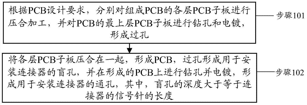
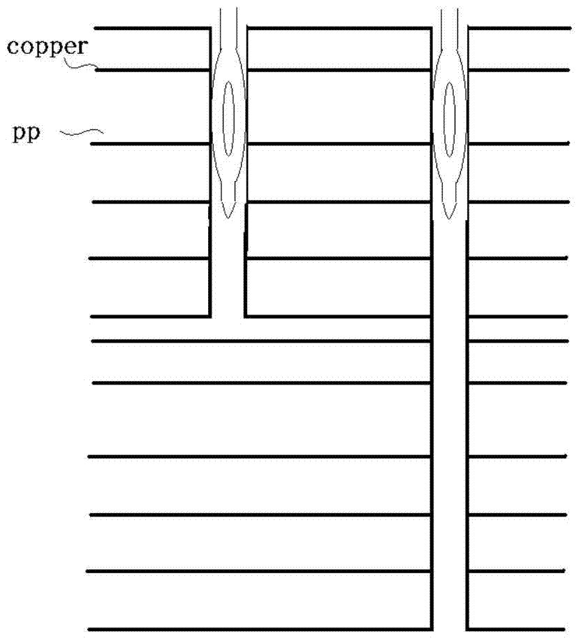
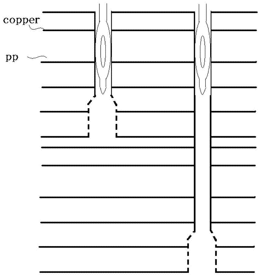
PCB processing method and PCB
A processing method and sub-board technology, which are applied in the mechanical removal of conductive materials, the formation of electrical connection of printed components, and the formation of printed circuits, which can solve problems such as poor control of short posts and space limitations for outgoing wires.
- Summary
- Abstract
- Description
- Claims
- Application Information
AI Technical Summary
Problems solved by technology
Method used
Image

Examples
Embodiment Construction
[0027] Exemplary embodiments of the present disclosure will be described in more detail below with reference to the accompanying drawings. Although exemplary embodiments of the present disclosure are shown in the drawings, it should be understood that the present disclosure may be embodied in various forms and should not be limited by the embodiments set forth herein. Rather, these embodiments are provided for more thorough understanding of the present disclosure and to fully convey the scope of the present disclosure to those skilled in the art.
[0028] As mentioned above, the connector installation in the prior art adopts the crimping method, and all the crimping holes are designed as through holes. The disadvantage of this method is that the distance between the two wafers of the connector is very close, resulting in a small space for the connector to go out. If you want to increase the outlet space, you have to sacrifice the density of the connector. In order to solve th...
PUM
 Abstract
Description
Claims
Application Information
 - R&D
- Intellectual Property
- Life Sciences
- Materials
- Tech Scout
- Unparalleled Data Quality
- Higher Quality Content
- 60% Fewer Hallucinations
Browse by: Latest US Patents, China's latest patents, Technical Efficacy Thesaurus, Application Domain, Technology Topic, Popular Technical Reports.
© 2025 PatSnap. All rights reserved.Legal|Privacy policy|Modern Slavery Act Transparency Statement|Sitemap|About US| Contact US: help@patsnap.com