Breaking roll grinding mill
A crushing roller and grinding technology applied to crushing roller grinding. It can solve the problems of poor grinding effect, unsuitable for food industry, easy to float in the air, etc., and achieve the effect of remarkable crushing effect, good grinding effect and good crushing effect.
- Summary
- Abstract
- Description
- Claims
- Application Information
AI Technical Summary
Problems solved by technology
Method used
Image
Examples
Embodiment 1
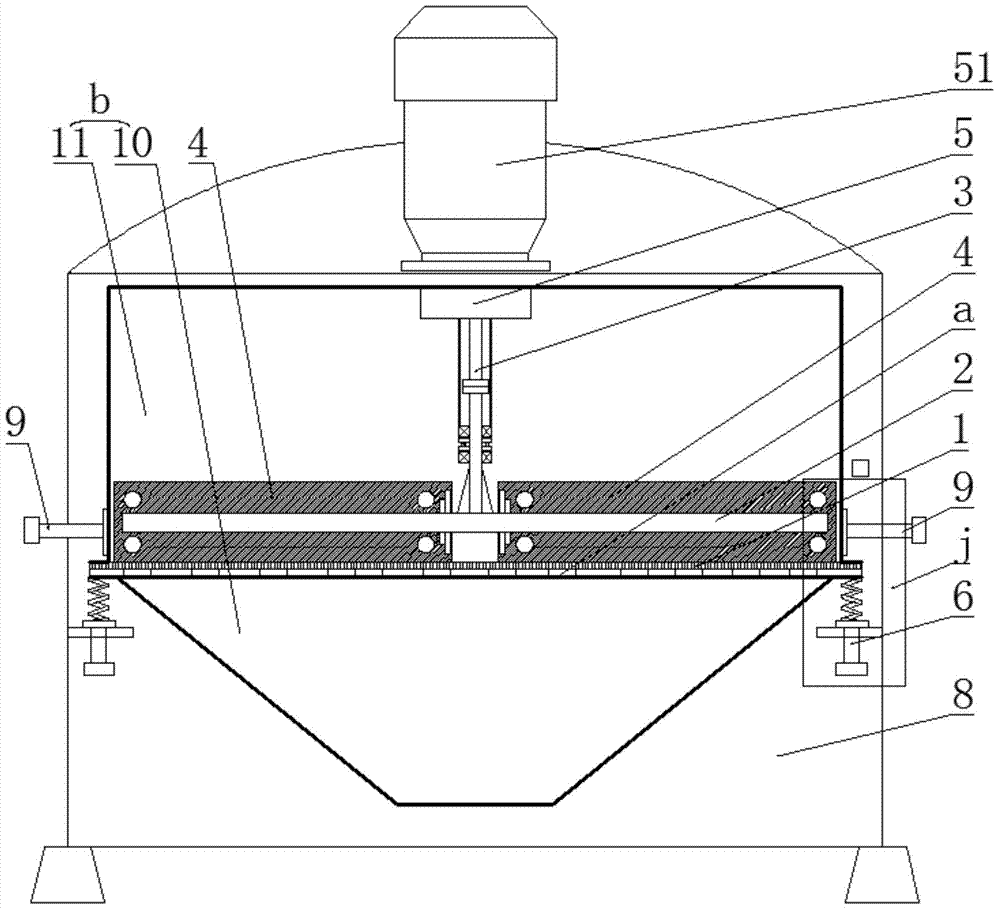
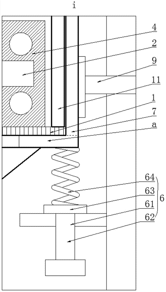
[0029] Such as figure 1 with figure 2 As shown, a crushing roller mill includes a sieve-shaped grinding disc 1, a horizontal roller shaft 2, a vertical rotating shaft 3, a roller 4, a power unit 5, an elastic support member 6, a disc support plate a, a grinding cylinder b and a support Protective tube 8, wherein:
[0030] At least three elastic supports 6 are provided on the inner wall of the support and protection cylinder 8, and the levels of the elastic supports 6 are consistent. The grinding cylinder b is arranged in the support and protection cylinder 8, and the grinding cylinder b passes through the The elastic support member 6 is held up, and the sieve-like grinding disc 1 and the grinding disc support plate a are arranged in the grinding cylinder b. The upper surface of the plate a is in close contact with the lower surface of the sieve-like milling pan 1, the sieve-like milling pan 1 is supported by the milling pan support plate a, and a finished screen hole is ope...
Embodiment 2
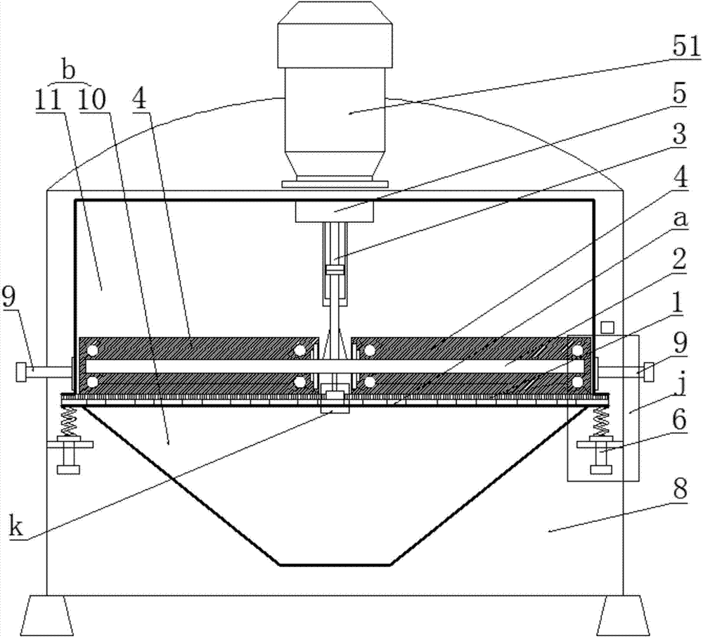
[0038] Such as image 3 , Figure 4 with Figure 5 As shown, the difference between this embodiment and Embodiment 1 is that the grinding cylinder b includes a raw material cylinder 11 and a finished product cylinder 10 located below the raw material cylinder 11, and the sieve-shaped grinding pan 1 and the grinding pan support plate a are located in the Between the raw material cylinder 11 and the finished product cylinder 10, the raw material cylinder 11 and the finished product cylinder 10 are connected by flanges and bolts. tight.
[0039] The power unit 5 includes a driving motor 51 arranged on the top of the supporting protective cylinder 8, the output shaft of the driving motor 51 is axially connected to the upper end of the vertical rotating shaft 3, and the driving motor 51 is a speed-regulating motor, The lower part of the vertical rotating shaft 3 is connected to the midpoint of the horizontal roller shaft 2, and a rotating shaft bearing seat x is provided at the ...
PUM
 Abstract
Description
Claims
Application Information
 - R&D
- Intellectual Property
- Life Sciences
- Materials
- Tech Scout
- Unparalleled Data Quality
- Higher Quality Content
- 60% Fewer Hallucinations
Browse by: Latest US Patents, China's latest patents, Technical Efficacy Thesaurus, Application Domain, Technology Topic, Popular Technical Reports.
© 2025 PatSnap. All rights reserved.Legal|Privacy policy|Modern Slavery Act Transparency Statement|Sitemap|About US| Contact US: help@patsnap.com


