Molten iron tank slag removal system and method

A technology for molten iron tanks and molten iron, applied in mechanical cleaning, manufacturing tools, metal processing equipment, etc., can solve problems such as eddy current slag rolling to the depth of molten iron, endangering the personal safety of operators, and failing to remove slag. Achieve the effects of shortening the slag removal time, short operation time and improving the slag removal effect

Active Publication Date: 2015-07-08
WISDRI ENG & RES INC LTD
View PDF16 Cites 7 Cited by
  • Summary
  • Abstract
  • Description
  • Claims
  • Application Information

AI Technical Summary

Problems solved by technology

The patent with the application number of 201120551436.1 discloses a blowing slag removal device. The slag removal gun does not extend into the molten iron, but blows air directly on the liquid surface of the molten iron. The slag force is weak and the slag is not easy to gather at the mouth of the tank. If the blowing flow rate is small, the effect of slag removal will not be achieved; if the blowing flow rate is large, it will easily cause eddy currents to engulf the slag to the depth of the molten iron and cannot be removed by the slag remover. In turn, the cleanliness of the molten iron is poor, and the molten iron splashes, burns the tip of the gun and even endangers the personal safety of the operator.
[0004] In addition, the arrangement of the slag removal device in the prior art adopts the method of extending the gun head from above the stirring position (where the molten iron tank is located when the molten iron is desulfurized), and the gun head must pass through the dust removal pipeline, which is not easy to install and affects the dust removal effect

Method used


Image

  • Molten iron tank slag removal system and method
  • Molten iron tank slag removal system and method
  • Molten iron tank slag removal system and method

Examples


Embodiment Construction

[0034] The following will clearly and completely describe the technical solutions in the embodiments of the present invention with reference to the accompanying drawings in the embodiments of the present invention. Obviously, the described embodiments are only some, not all, embodiments of the present invention. Based on the embodiments of the present invention, all other embodiments obtained by persons of ordinary skill in the art without making creative efforts belong to the protection scope of the present invention.

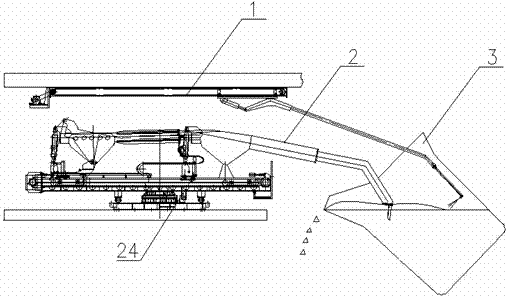
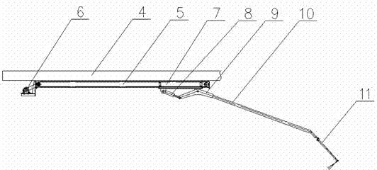
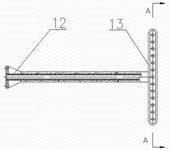
[0035] Such as Figure 1-Figure 7 , the embodiment of the present invention provides a molten iron tank slag removal system, including air blowing slag removal device 1 and slag removal device; The slag removal machine 2 moving on the track. The air blowing slag removal device 1 includes an air blowing slag removal gun and a positioning mechanism for positioning the position of the air blowing slag removal gun; the air blowing slag removal gun includes a holl...


PUM


Abstract

The invention relates to a molten iron tank slag removal system which comprises a blowing and slag catching device. The blowing and slag catching device comprises a blowing slag catching gun and a positioning mechanism for positioning the blowing slag catching gun. The blowing slag catching gun comprises a gun head. The gun head comprises a hollow gun barrel, a gas distributor connected with the gun barrel and a plurality of nozzles. The gas distributor comprises an arc cavity. The nozzles are arranged along the inner arc face of the arc cavity at intervals. The blowing directions of all the nozzles are on the same plane. An included angle is formed between the plane and the length direction of the gun barrel. The invention further relates to a molten iron tank slag removal method. The method uses the molten iron tank slag removal system for slag removal. According to the molten iron tank slag removal system and method, the operation time is short, iron losses are low, the blowing quantity can be lowered, the operation cost is low, and the slag removal work is safer and more reliable.

Description

technical field [0001] The invention relates to the technical field of molten iron pretreatment, in particular to a molten iron tank slag removal system and a molten iron tank slag removal method. Background technique [0002] Desulfurization of molten iron is a necessary link in the steelmaking process. After desulfurization of molten iron, a large amount of slag floats on the surface of molten iron. Rapid slag removal can shorten the desulfurization cycle, gain time for other links in the steelmaking cycle, and reduce the workload of operators at the same time. Improving the cleanliness of slag removal can reduce sulfur return and improve desulfurization effect. Reducing the iron loss of desulfurization and slag removal can save production cost and improve efficiency. Therefore, inventing a method for fast slag removal, which can improve the cleanliness of slag removal and reduce iron loss at the same time, has very positive significance for improving the product quality...

Claims


Application Information

Patent Timeline
IPC IPC(8): B22D43/00C21C1/02
Inventor 袁金生黄俊王少强张文封伟华
Owner WISDRI ENG & RES INC LTD
Why Eureka
Try Eureka