Optical engine timing mechanism, optical engine timing method and optical engine

A technology of optical engine and timing mechanism, which is applied in the direction of engine components, machines/engines, mechanical equipment, etc., can solve the problems of incorrect determination of timing results, danger of piston top valve, time-consuming and labor-intensive problems, and achieve improved timing accuracy and connection High-intensity, easy-to-use effects

Inactive Publication Date: 2015-07-08
CHERY AUTOMOBILE CO LTD
View PDF7 Cites 8 Cited by
  • Summary
  • Abstract
  • Description
  • Claims
  • Application Information

AI Technical Summary

Problems solved by technology

However, since the spray and combustion in the optical engine will cause dirt and soot on the transparent cylinder liner and the top surface of the transparent piston, it is necessary to disassemble the optical engine for cleaning after running for 1-2 hours to ensure the test results. The disassembly and assembly process needs to involve re-selecting the timing position setting of the crankshaft and camshaft of the engine. The traditional timing position of the crankshaft and camshaft is determined by using the tooling plug on the cylinder block to find the processing on the crankshaft mating block. Ho

Method used


Image

  • Optical engine timing mechanism, optical engine timing method and optical engine
  • Optical engine timing mechanism, optical engine timing method and optical engine
  • Optical engine timing mechanism, optical engine timing method and optical engine

Examples


Embodiment Construction

[0027] The technical solutions of the present invention will be described in detail below in conjunction with the accompanying drawings, so that those skilled in the art can understand the present invention more clearly, but the protection scope of the present invention is not limited thereby.

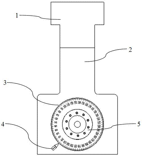
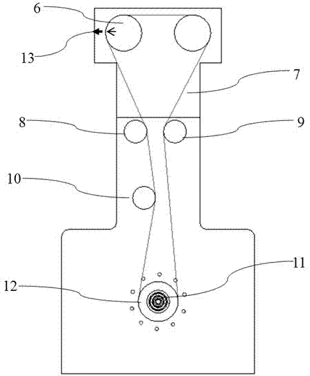
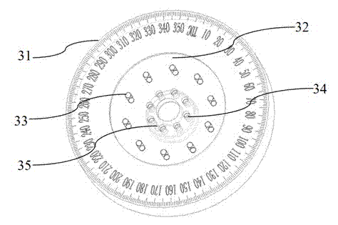
[0028] The timing mechanism of the optical engine of the present invention is as attached figure 1 to attach image 3 As shown, it includes flywheel assembly 3, crankshaft positioning pointer 4, timing gear 6, timing belt 7, first fixed idler 8, second fixed idler 9 and timing belt tensioner 10. The optical engine of the timing mechanism includes a cylinder head assembly 1, a cylinder block assembly 2, a crankshaft 11, a coupling flange 5, a crankshaft pulley 12 and a dynamometer. The specific schematic structure of the optical engine is shown in the attached figure 1 And attached figure 2 As shown, the cylinder head assembly 1 includes a cylinder head body, a transparent cylinder l...


PUM


Abstract

The invention discloses an optical engine timing mechanism, an optical engine and an optical engine timing method. A flywheel assembly is introduced into a cylinder body of the optical engine, the flywheel assembly is connected with a crankshaft and a power measurer, the plane outer of the flywheel assembly is provided with a 0-360-degree crankshaft rotary angle scale plate; a crankshaft positioning pointer is used for pointing timing indicator scale position on the scale plate to determine an upper stop point position of the piston, and is matched with a cam shaft, the timing gear and a corresponding timing indicator position on the cylinder to realize selecting an optical engine timing position, so that the timing position determination of the optical engine is realized in a relatively visual, convenient and precise mode, and the dismounting and mounting efficiency of the optical engine is improved.

Description

technical field [0001] The invention relates to the field of engines, in particular to the timing technology of engine crankshafts, and more specifically to an optical engine timing mechanism, an optical engine timing method and an optical engine. Background technique [0002] At present, the optical engine is mainly used to study the combustion spray, flame propagation, and soot generation in the cylinder of the engine. This type of optical engine mostly uses a partially transparent cylinder liner and a transparent piston top surface structure, and collects the spray and spray in the cylinder through a CCD camera. Combustion situation, the operation of the optical engine is to use the dynamometer to drag and rotate, and control the ignition and combustion of the optical engine by controlling the ignition of the spark plug and the fuel injection of the fuel injector. In most cases, the optical engine is dragged by the dynamometer running. However, since the spray and combus...

Claims


Application Information

Patent Timeline
IPC IPC(8): F01L1/348
CPCF02B77/087
Inventor 琚雪明刘华龙鲁新耀
Owner CHERY AUTOMOBILE CO LTD
Why Eureka
Try Eureka