Laser surface treatment quality control method and on-line monitoring system thereof

A technology of laser surface treatment and quality control method, which is applied in the direction of laser welding equipment, manufacturing tools, welding equipment, etc., can solve the problems of damaged coating, unguaranteed quality, and different processing quality, so as to avoid great loss and guarantee Reliability and processing efficiency, effect of reducing problems

Active Publication Date: 2015-07-15
BAOSHAN IRON & STEEL CO LTD
View PDF4 Cites 19 Cited by
  • Summary
  • Abstract
  • Description
  • Claims
  • Application Information

AI Technical Summary

Problems solved by technology

This technology has the following disadvantages: 1) Since the power of each laser and the focusing lens cannot be completely consistent, the scanning line segments on the workpiece cannot be completely consistent, which will lead to the final processing of each position on the terminal. The processing quality is not the same; 2) Due to the large number of lasers required, especially when the workpiece is dynamic and moving at a high speed, even hundreds of lasers are required. Such a large number of lasers will undoubtedly increase the difficulty of on-site monitoring and maintenance ;3) The surface of some processed parts will be coated

Method used


Image

  • Laser surface treatment quality control method and on-line monitoring system thereof
  • Laser surface treatment quality control method and on-line monitoring system thereof
  • Laser surface treatment quality control method and on-line monitoring system thereof

Examples


Embodiment Construction

[0032] In order to make the above objects, features and advantages of the present invention more comprehensible, specific implementations of the present invention will be described in detail below in conjunction with the accompanying drawings. First of all, it should be noted that the present invention is not limited to the following specific embodiments. Those skilled in the art should understand the present invention from the spirit embodied in the following embodiments, and each technical term can be optimized based on the spirit of the present invention. broad understanding. The same or similar components in the figures are denoted by the same reference numerals.

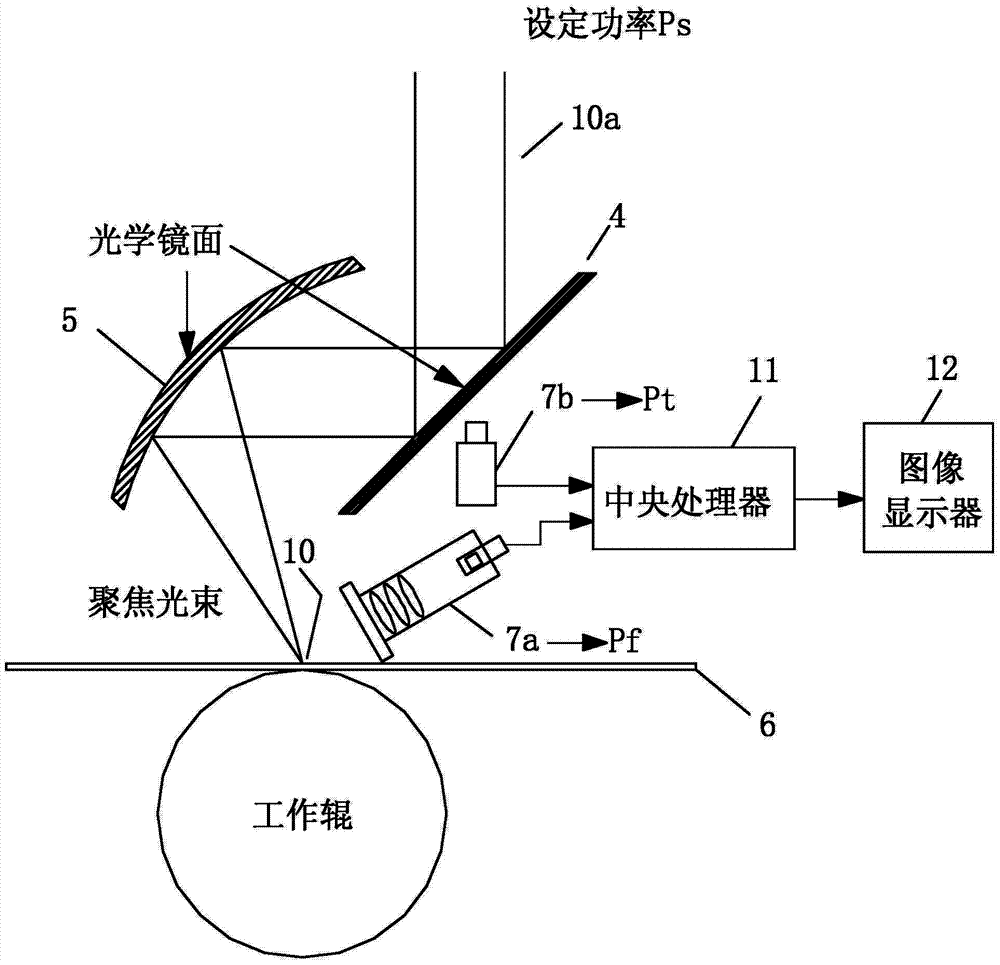
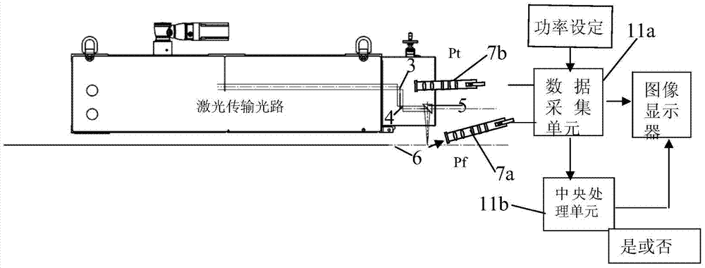
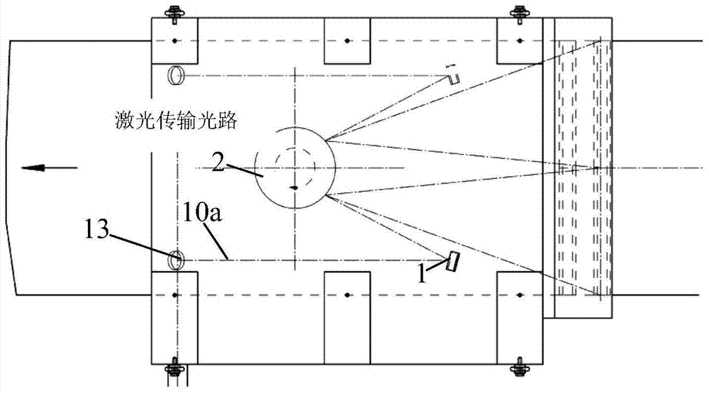
[0033] A kind of laser surface treatment quality control method according to an embodiment of the present invention, such as figure 1 , figure 2 image 3As shown, it is implemented by an online monitoring system, which includes a laser transmission optical system, a central processing unit 11 and an image di...


PUM


Abstract

The invention provides a laser surface treatment quality control method and an on-line monitoring system thereof. The laser surface treatment quality control method comprises the steps that incident laser is emitted through a laser, passes through an inner transmission light path, and at last is focused on a workpiece through a focus lens; the light reflected on the surface of the workpiece in practical processing is detected through a first photoelectric sensor; the light is converted to be a reflective power value through photovoltaic conversion; the residual penetration light of the reflective lens surface of a reflective lens in the transmission light path is detected through a second photoelectric sensor to obtain the practical power; parameters, set power, the reflective power value and the practical power are sent to a central processing unit to be subjected to comparison calculation through a data collection unit, and a mass control factor is determined through logic judgment; the mass control real-time information is displayed through an image display device. The invention guarantees the high consistence of laser power density of the laser in the material surface treatment process and the accuracy of the height position of a laser focal point on a material surface.

Description

technical field [0001] The invention relates to a laser surface treatment quality control method and a control system thereof. Background technique [0002] Laser surface treatment technology is a cutting-edge technology that has gradually emerged in recent years. Its application prospects are very broad, especially in metal surface treatment. To put it simply, the principle of this technology is to use the laser beam to quickly scan the object to be processed, so that the surface of the workpiece can be melted rapidly or form physical features such as grooves on the surface through thermal stress, or form thin layers of different depths. to replace mechanical surface treatment or chemical surface treatment. Subsequent methods such as vacuum evaporation, electroplating, etc. can be used to coat the alloy elements on the surface of the workpiece, fully fuse with the base metal under laser irradiation, and obtain an alloy layer with special properties after condensation. For...

Claims


Application Information

Patent Timeline
IPC IPC(8): B23K26/352B23K26/046B23K26/062
CPCB23K26/046B23K26/0626B23K26/352
Inventor 毛兴宋俊杨建林
Owner BAOSHAN IRON & STEEL CO LTD
Why Eureka
Try Eureka