Pinhole inspection device for can body

A technology for inspection devices and tanks, which is applied in the direction of measuring devices, application of light to test fluid tightness, and optical testing of flaws/defects, etc. It can solve the problem of increased occurrence rate of false detection, lack of detectable light quantity, and functional effects Issues such as not fully explained, achieve the effects of improving shading, preventing interference light from reaching the photodetector side, and uniform friction

Active Publication Date: 2015-07-15
TOYO SEIKAN GRP HLDG LTD
View PDF6 Cites 0 Cited by
  • Summary
  • Abstract
  • Description
  • Claims
  • Application Information

AI Technical Summary

Problems solved by technology

[0008] In addition, the light-shielding part described in Patent Document 3 adopts a complicated structure in which the opposing fixed-side disk is embedded in a peripheral groove, so its position adjustment is difficult. In addition, the specification also discloses that a The return bending of light to the direction of intrusion, but its effect has not been fully explained, and the above problems have not been fully resolved
[0009] In addition, in terms of the performance of the photodetector, the pinhole diameter of the inspection target of the existing pinhole inspection device for cans is about 20 μm. The light that penetrates the tank through the hole becomes weak, and there is a concern that the amount of light that cannot be detected will not be achieved
Here, a method of ensuring the amount of light detectable by the photodetector by using a light source with a higher brightness than before is considered, but in the existing device structure, countermeasures against disturbing light are not sufficiently taken, and there are errors caused by an increase in the amount of light. Concerns about rising rates of testing

Method used


Image

  • Pinhole inspection device for can body
  • Pinhole inspection device for can body
  • Pinhole inspection device for can body

Examples


Embodiment Construction

[0045] One embodiment of the pinhole inspection device for can bodies according to the present invention will be described.

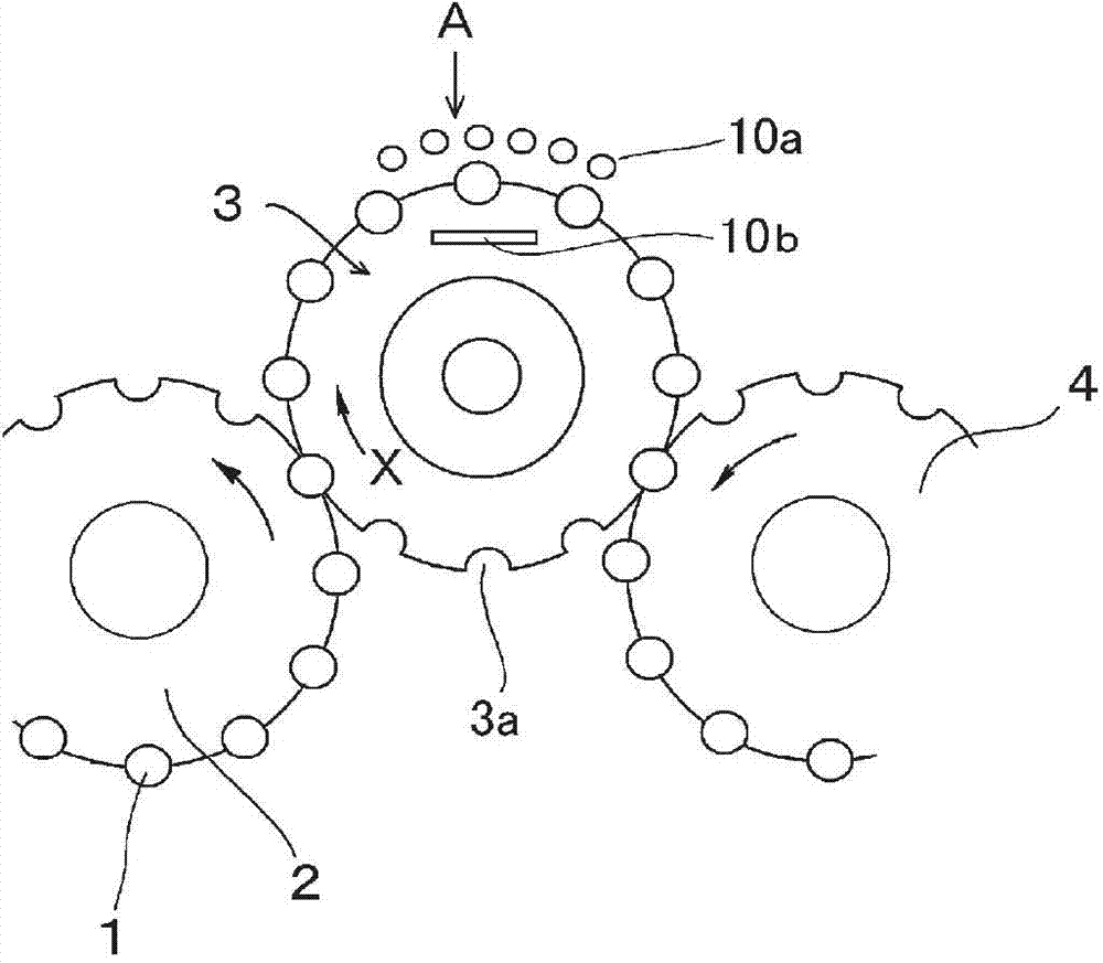
[0046] Such as figure 1 As shown, for the pinhole inspection device for can bodies of the present invention, the can body 1 supplied from the supply turntable 2 to the recess 3a of the holding turntable 3 continuously rotating in the X direction is transported to the upper light source 10a which will be described later. , the inspection station A of the lower light source 10b (hereinafter also referred to as the light source 10 ) and after the good or bad judgment has been carried out, it is sent out to the next process by the sending out turntable 4 .

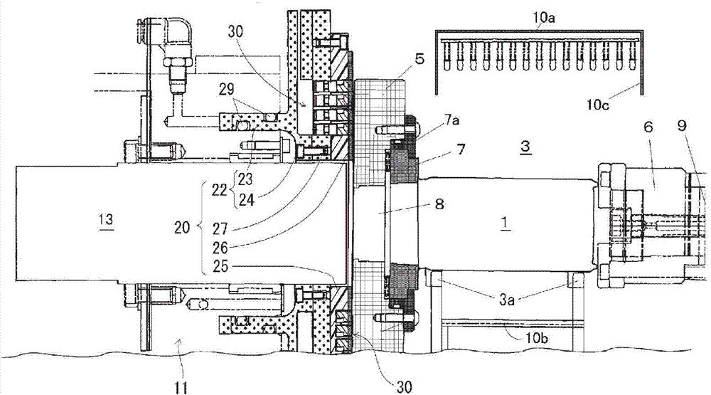
[0047] And, if figure 2 As shown, the pinhole inspection device for cans of the present invention includes a holding turntable 3, a rotating plate 5, a chuck 6, an upper light source 10a, and a lower light source 10b, and the holding turntable 3 and the rotating plate 5 constitute an inspection turnt...


PUM

PropertyMeasurementUnit
thicknessaaaaaaaaaa

Abstract

The present invention provides a pinhole inspection apparatus for can bodies including a rotary plate having a penetrating through hole, a movable plate provided on a stationary frame opposite the rotary plate, a can body holding member that holds a can body, a photodetector that detects light leaking inside the can body, and a light source that irradiates an outer circumferential surface of the can body with light. The movable plate includes a ring plate attached to a front surface of a piston member, which has a penetrating hole in a central portion thereof, via a joint member. The ring plate is provided with a shield member formed by an annular member that is formed concentric to the penetrating hole. The shield member is brought into sliding contact with the rotary plate by a pressure application mechanism. With this apparatus, ambient light can be effectively prevented from reaching a photodetector side through a gap between the movable plate and rotary plate that may be formed due to external force, or a surface condition of a sealing ring plate and a sliding ring plate.

Description

technical field [0001] The present invention relates to an inspection device for inspecting pinholes formed in the main body of a can body or the like. Background technique [0002] In the manufacturing process of metal cans such as seamless cans (hereinafter simply referred to as cans) produced by deep drawing and thinning, pinholes such as holes and cracks may occur in the main body of the above-mentioned cans. . The presence or absence of the above-mentioned pinholes is generally inspected by a pinhole inspection device used in the above-mentioned inspection process of the can body. [0003] Such as Figure 10 As shown, the pinhole inspection device shown in Patent Document 1 is configured as follows: the right side is an inspection turntable holding the can body to be inspected, and the left side is a can body internal light detection device. In addition, the piston-shaped sealing portion to which the sealing ring plate is fixed is provided so as to be in slidable cont...

Claims


Application Information

Patent Timeline
Patent Type & Authority Applications(China)
IPC IPC(8): G01N21/90
CPCG01N21/909G01N21/894G01M3/38G01N21/90
Inventor 小路泰广濑尾友规石井佑直
Owner TOYO SEIKAN GRP HLDG LTD
Why Eureka
Try Eureka