
Aeration rate control method and system

A control method and aeration rate technology, applied in the direction of using electric device flow control, sustainable biological treatment, aerobic process treatment, etc., can solve the problem of DO stability and control, and the accuracy cannot properly solve the influence of DO signal time lag , The effect of sewage treatment is difficult to meet expectations, etc., to achieve stable dissolved oxygen concentration, real-time precise adjustment, and stable and effective sewage treatment effect

Active Publication Date: 2015-07-22
梁锐振
View PDF4 Cites 23 Cited by
  • Summary
  • Abstract
  • Description
  • Claims
  • Application Information

AI Technical Summary

Problems solved by technology

This control idea has two defects: first, the accuracy of the calculation results depends on whether the collected signals are sufficient and accurate, whether the identification of water quality proportional parameters is accurate, whether the identification of biochemical kinetic parameters is accurate, and whether the efficiency setting of oxygenation equipment is accurate and many other factors. Second, the accuracy of the execution of the calculation results is affected by the execution control logic level, and the time-lag effect of the DO signal cannot be properly resolved. Therefore, it is difficult to guarantee the stability and control of DO.
[0007] In summary, the aeration rate control methods in the prior art are difficult to achieve stable control of DO (dissolved oxygen concentration) in the water body, and the sewage treatment effect is difficult to meet expectations

Method used


Image

  • Aeration rate control method and system
  • Aeration rate control method and system
  • Aeration rate control method and system

Examples


Embodiment 1

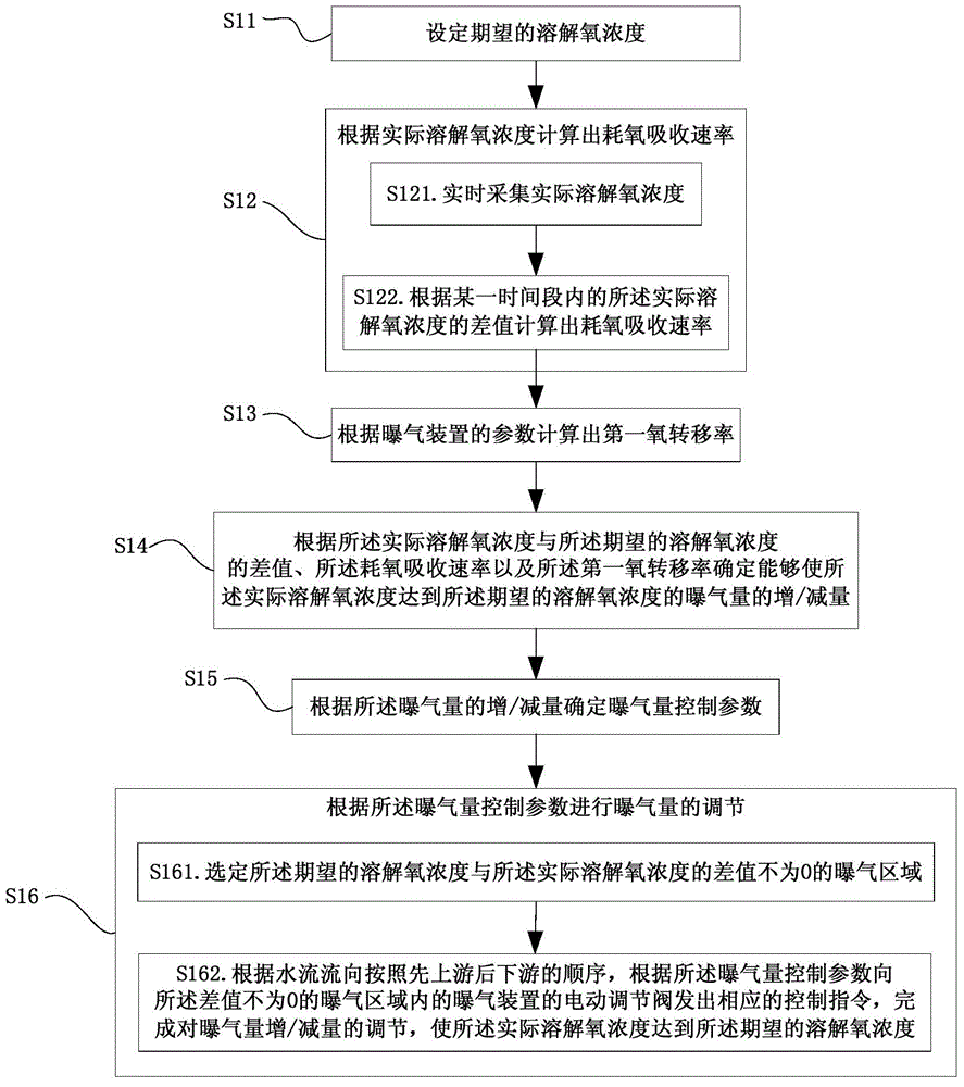
[0053] This embodiment provides a method for controlling the amount of aeration, such as figure 1 shown, including:

[0054] S11. Set the desired dissolved oxygen concentration.

[0055] S12. Calculate the oxygen consumption absorption rate according to the actual dissolved oxygen concentration.

[0056] S13. Calculate the first oxygen transfer rate according to the parameters of the aeration device.

[0057] S14. According to the difference between the actual dissolved oxygen concentration and the expected dissolved oxygen concentration, the oxygen consumption absorption rate and the first oxygen transfer rate, determine that the actual dissolved oxygen concentration can reach the expected dissolved oxygen concentration. The increase / decrease of the aeration rate of the oxygen concentration.

[0058] S15. Determine an aeration rate control parameter according to the increase / decrease of the aeration rate.

[0059] S16. Adjust the aeration amount according to the aeration ...

Embodiment 2

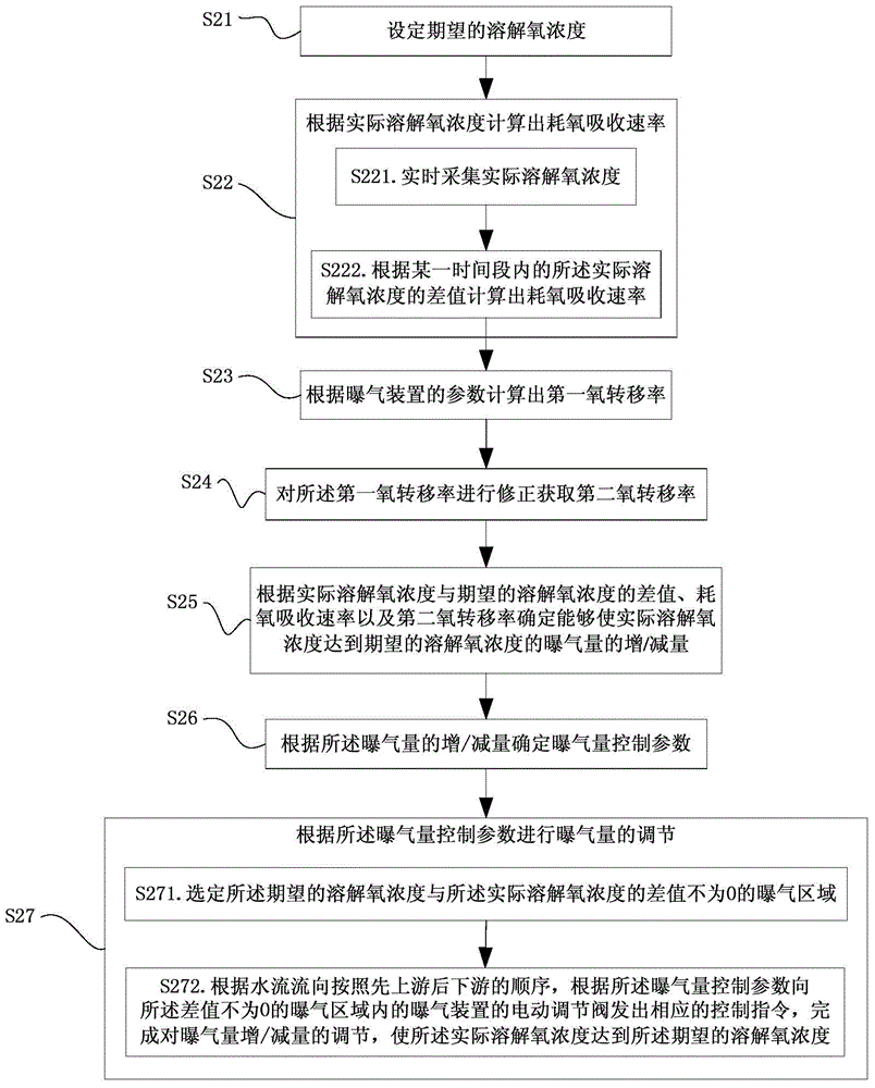
[0089] On the basis of Example 1, this example optimizes the aeration rate control method, such as figure 2 shown, including:

[0090] S21. Setting a desired dissolved oxygen concentration.

[0091] S22. Calculate the oxygen consumption absorption rate according to the actual dissolved oxygen concentration.

[0092] S23. Calculate the first oxygen transfer rate according to the parameters of the aeration device.

[0093] S24. Correcting the first oxygen transfer rate to obtain a second oxygen transfer rate.

[0094] S25. According to the difference between the actual dissolved oxygen concentration and the expected dissolved oxygen concentration, the oxygen consumption absorption rate and the second oxygen transfer rate, determine that the actual dissolved oxygen concentration can reach the expected dissolved oxygen concentration. The increase / decrease of the aeration rate of the oxygen concentration. Specifically, when the difference is positive and not within the preset ...

Embodiment 3

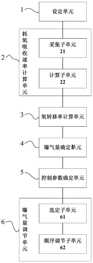
[0105] This embodiment provides an aeration volume control system, such as image 3 shown, including:

[0106] The setting unit 1 is used to set the desired dissolved oxygen concentration.

[0107] The oxygen consumption absorption rate calculation unit 2 is used to calculate the oxygen consumption absorption rate according to the actual dissolved oxygen concentration.

[0108] The oxygen transfer rate calculation unit 3 is used to calculate the first oxygen transfer rate according to the parameters of the aeration device.

[0109] The aeration rate determination unit 4 is configured to determine the actual dissolved oxygen concentration according to the difference between the actual dissolved oxygen concentration and the expected dissolved oxygen concentration, the oxygen consumption absorption rate and the first oxygen transfer rate. The increase / decrease of the aeration rate for the concentration to reach the desired dissolved oxygen concentration.

[0110] The control p...


PUM


Abstract

The invention provides an aeration rate control method and system. The method comprises the following steps: setting an expected dissolved oxygen concentration, calculating first oxygen transfer ratio on the basis of parameters of the aeration device according to the difference between the actual dissolved oxygen concentration and expected dissolved oxygen concentration, determining the aeration rate increment / decrement capable of enabling the actual dissolved oxygen concentration to reach the expected dissolved oxygen concentration according to the difference between the expected dissolved oxygen concentration and actual dissolved oxygen concentration, the oxygen consumption absorption rate and the first oxygen transfer ratio, determining the aeration rate control parameters according to the aeration rate increment / decrement, and adjusting the aeration rate according to the aeration rate control parameters. Therefore, according to the aeration rate control method and system, the difference between the expected dissolved oxygen concentration and actual dissolved oxygen concentration, the oxygen consumption absorption rate and the first oxygen transfer ratio are utilized to determine the aeration rate increment / decrement capable of enabling the actual dissolved oxygen concentration to reach the expected dissolved oxygen concentration, thereby implementing the real-time accurate adjustment on the aeration rate. Thus, the sewage treatment effect is more stable and effective.

Description

technical field [0001] The invention relates to the technical field of sewage treatment, in particular to an aeration control method and system. technical background [0002] In the current field of sewage treatment, the biological method is the most widely used, that is, by artificially maintaining an aerobic, anoxic or anaerobic environment, the microorganisms in the biological pool can continue to undergo specific biochemical reactions according to the needs to reduce the concentration of target pollutants. Such as reducing the concentration of BOD5, COD, TP, TN and other pollutants in the water, so as to achieve discharge standards. The aeration rate is the primary factor affecting the effect of biological treatment. The control level of aeration rate determines the treatment effect of sewage to a large extent, and it is also the most important energy consumption unit, generally accounting for 45% of the energy consumption of the plant—— 70%. In practical application, ...

Claims


Application Information

Patent Timeline
Patent Type & Authority Applications(China)
IPC IPC(8): C02F3/02G05D7/06
CPCY02W10/10
Inventor 梁锐振
Owner 梁锐振
Learn More