Equal optical path position adjusting method of optical fiber point diffraction interferometer

A technology of point diffraction interferometer and adjustment method, which is applied in the field of optical measurement, can solve the problems of high price, large size and inconvenient LenScan, and achieve the effect of simple operation, high precision and high efficiency

Active Publication Date: 2015-07-22
CHANGCHUN INST OF OPTICS FINE MECHANICS & PHYSICS CHINESE ACAD OF SCI
View PDF5 Cites 14 Cited by
  • Summary
  • Abstract
  • Description
  • Claims
  • Application Information

AI Technical Summary

Problems solved by technology

However, LenScan is used to measure the distance between lenses, it is expensive, and LenScan has a large volume, and there are many inconveniences in adjusting the optical path position directly for fiber point diffraction interferometers.

Method used


Image

  • Equal optical path position adjusting method of optical fiber point diffraction interferometer
  • Equal optical path position adjusting method of optical fiber point diffraction interferometer

Examples


Embodiment Construction

[0018] The present invention will be described in further detail below in conjunction with the accompanying drawings and embodiments.

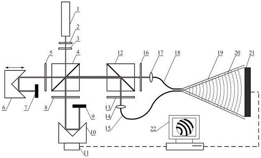
[0019] Such as figure 1 As shown, the optical path position adjustment method such as fiber optic point diffraction interferometer, the method includes the following components: laser 1, neutral density filter 2, 1 / 2 wave plate 3, first polarization beam splitter prism 4, first 1 / 2 4 wave plate 5, first corner cube prism 6, first plane mirror 7, second 1 / 4 wave plate 8, second plane mirror 9, second corner cube prism 10, piezoelectric ceramic 11, second polarizer Dichroic prism 12, second polarizer 13, second coupling lens 14, second optical fiber 15, first polarizer 16, first coupling lens 17, first optical fiber 18, first optical fiber diffraction spherical wave 19, second optical fiber diffraction Spherical wave 20, CCD detector 21, computer 22. Include the following steps:

[0020] Step 1: After the laser light emitted by the short cohe...


PUM


Abstract

An equal optical path position adjusting method of an optical fiber point diffraction interferometer relates to the technical field of optical measurement. The method can effectively judge whether reference light and testing light have the equal optical path or not and has a relatively low price. A polarization splitting prism, two polarization sheets, two coupling lenses and two optical fibers are additionally arranged behind a first polarization splitting prism; optical path conditions of the reference light and the testing light are reflected on an interference pattern and the optical path difference of the reference light and the testing light is judged by the contrast ratio of the interference pattern, which is a direct physical amount; an optical method, but not a mechanical method, is used for adjusting an equal optical path position, so that the optical path conditions of the reference light and the testing light are quantitatively given; the equal optical path position adjusting method has the advantages of high precision, high efficiency, simplicity in operation and the like.

Description

technical field [0001] The invention relates to the technical field of optical measurement, in particular to a method for adjusting the optical path position of an optical fiber point diffraction interferometer. Background technique [0002] Extreme Ultraviolet Lithography (EUVL) is the best candidate technology for the next-generation lithography technology, suitable for the manufacture of several generations of ultra-large-scale integrated circuits at 22nm and below. Form the image onto the wafer. Due to the characteristics of the EUV band, the EUVL projection exposure objective lens system must adopt a total reflection optical system. In order to make the graphics on the mask nearly perfect on the wafer, the projection exposure objective lens system is required to have a diffraction-limited resolution. According to the Marachel criterion, the wave aberration of the projection exposure objective lens system is about 1.0nm. RMS. The traditional commercial Fizet interfero...

Claims


Application Information

Patent Timeline
Patent Type & Authority Applications(China)
IPC IPC(8): G01J9/02
Inventor 金春水卢增雄马冬梅张海涛于杰
Owner CHANGCHUN INST OF OPTICS FINE MECHANICS & PHYSICS CHINESE ACAD OF SCI
Why Eureka
Try Eureka