
Temperature sensor system and method for producing a temperature sensor system

A technology of temperature sensor and thermometer element, which is applied to the parts of thermometers, thermometers, and thermometers using electric/magnetic elements directly sensitive to heat, etc., which can solve problems such as delayed response time, and achieve precise shell size structure, high mechanical and chemical fastness, effect of short response time

Inactive Publication Date: 2015-07-22
EPCOS AG
View PDF12 Cites 1 Cited by
  • Summary
  • Abstract
  • Description
  • Claims
  • Application Information

AI Technical Summary

Problems solved by technology

Another big drawback of the system constructed in this way is its delayed response time due to the heat conduction caused by the additional structure and the low heat conductivity of the materials used

Method used


Image

  • Temperature sensor system and method for producing a temperature sensor system
  • Temperature sensor system and method for producing a temperature sensor system
  • Temperature sensor system and method for producing a temperature sensor system

Examples


Embodiment Construction

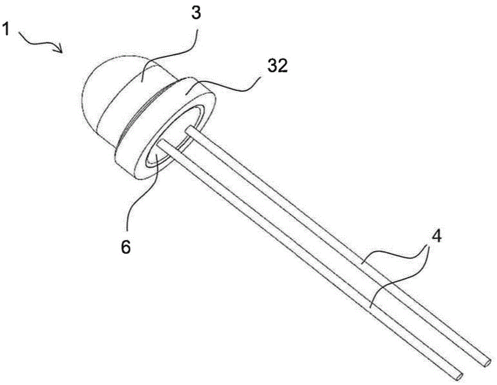
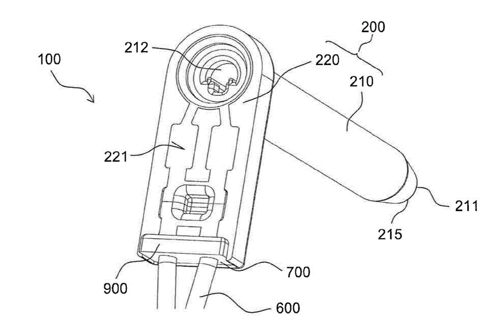
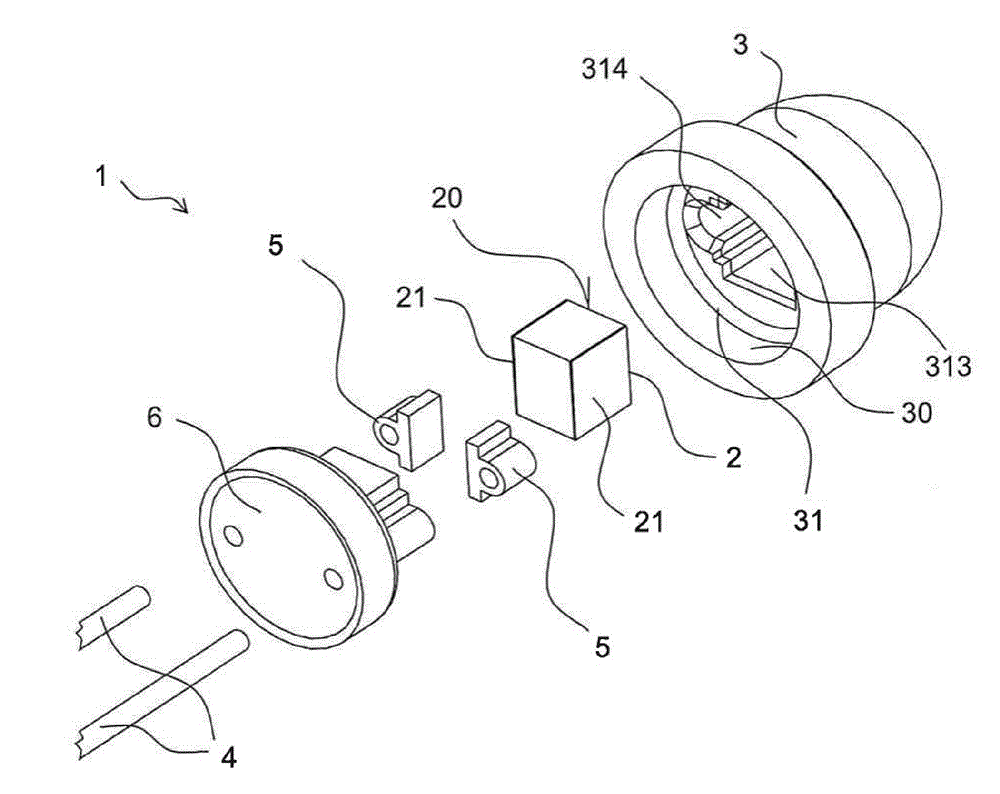
[0057] Figures 1 to 4 Various views of the temperature sensor system 100 described here are shown according to an exemplary embodiment. exist image 3 The temperature sensor system 100 in is shown without the second ceramic housing part 300 . Figure 5 show Figures 1 to 4 A cross-sectional view of the temperature sensor system 100 and the Figure 6 The medium temperature sensor system 100 is shown in exploded view. The description below also covers Figures 1 to 6 .

[0058] The temperature sensor system 100 has a first ceramic housing part 200 . The first ceramic housing part 200 has a sleeve-shaped lower part 210 with a first lower end 215 having a first opening 211 and a second upper end 216 having a second opening 212, and a second upper end 216 with the second upper end. The upper part 220 to which the part 216 is connected. The sleeve-shaped lower part 210 and the upper part 220 together form an "L-shaped" body, which is formed in one piece. The first ceramic ...


PUM

PropertyMeasurementUnit
service temperatureaaaaaaaaaa
thicknessaaaaaaaaaa
thicknessaaaaaaaaaa

Abstract

The invention relates to a temperature sensor system (100) comprising a first ceramic housing part (200) which has a sleeve-shaped lower part (210) with a first lower end (215) having a first opening (211), and a second upper end (216) having a second opening (212), and an upper part (220) connected to the second upper end (216). The temperature sensor system (100) further comprises a temperature probe element (1) which is at least partially arranged in the lower part (210) and which has a ceramic sensor element housing (3), a sensor element (2) arranged in the sensor element housing (3) and electrical supply lines (4). The sensor element housing (3) is at least partially arranged in the first opening (211). The ceramic sensor element housing (3) has a higher thermal conductivity than the first ceramic housing part (200). Also disclosed is a method for producing a temperature sensor system (100).

Description

Background technique [0001] For example via ceramic heating conductors - thermistor elements (NTC thermistors, "negative temperature coefficient thermistors"), silicon temperature sensors (e.g. so-called KTY temperature sensors), platinum temperature sensors (PRTD, "platinum temperature sensors") resistance temperature detectors") or thermocouples (TC, "thermocouples") in order to monitor and regulate the measured temperature in different applications. [0002] For easy assembly in the application, sufficient mechanical stability, and to protect the own temperature sensor element from external influences, and to avoid corrosion due to aggressive media, it is mounted inside a housing, which is generally made of plastic, of simple metal construction or of Composition of plastic-metal composites. Plug contacts and / or conductor vias are generally integrated into the housing for the electrical connection. A suitable sealing of such systems is achieved using sealing, potting compo...

Claims


Application Information

Patent Timeline
Patent Type & Authority Applications(China)
IPC IPC(8): G01K1/08
CPCG01K1/08G01K7/22
Inventor J.伊勒O.巴尔德G.克洛伊贝尔
Owner EPCOS AG
Learn More