A bionic undulating long-fin underwater propeller
What is Al technical title?
Al technical title is built by PatSnap Al team. It summarizes the technical point description of the patent document.
A technology of thrusters and long fins is applied in the field of bionic robotic fish, which can solve the problems of difficulty in realizing rapid underwater three-dimensional motion, limited guiding role of underwater thrusters, and restrictions on the types of motion of robotic fish, so as to improve energy utilization efficiency and weight. The effect of reduction, volume reduction
Active Publication Date: 2017-03-08
INST OF AUTOMATION CHINESE ACAD OF SCI
View PDF7 Cites 1 Cited by
Summary
Abstract
Description
Claims
Application Information
AI Technical Summary
This helps you quickly interpret patents by identifying the three key elements:
Problems solved by technology
Method used
Benefits of technology
Problems solved by technology
[0005] The above-mentioned long fin propulsion device can realize forward and backward motion, but the swimming speed is relatively slow. Due to structural limitations, it is difficult to realize fast three-dimensional underwater motion, and the scalability is not strong, so it has limited guidance for the development of new underwater propellers
The Institute of Automation of the Chinese Academy of Sciences has imitated rays to develop a bionic robot fish propelled by pectoral fin fluctuations, which can realize multi-modal movements such as forward, backward, rising, and diving. less, the fin surface can only achieve a sine wave fluctuation at most, and the types of motion that the robot fish can perform are limited
Method used
Image
Click on the blue label to locate the original text in one second.
Reading with bidirectional positioning of images and text.
Examples
Embodiment Construction
[0023] In order to make the object, technical solution and advantages of the present invention clearer, the present invention will be further described in detail below in conjunction with specific embodiments and with reference to the accompanying drawings.
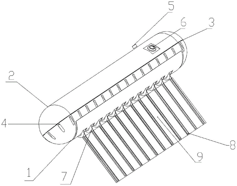
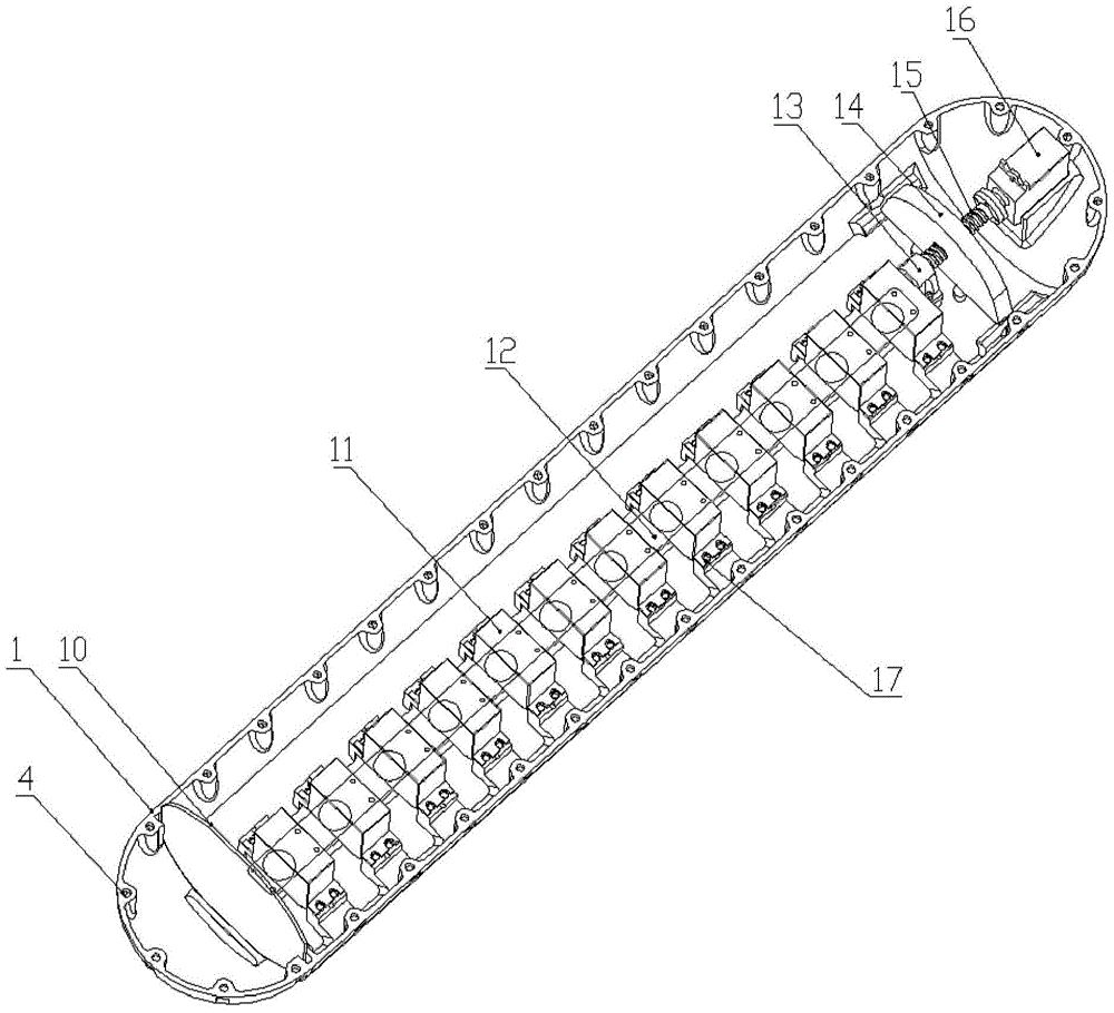
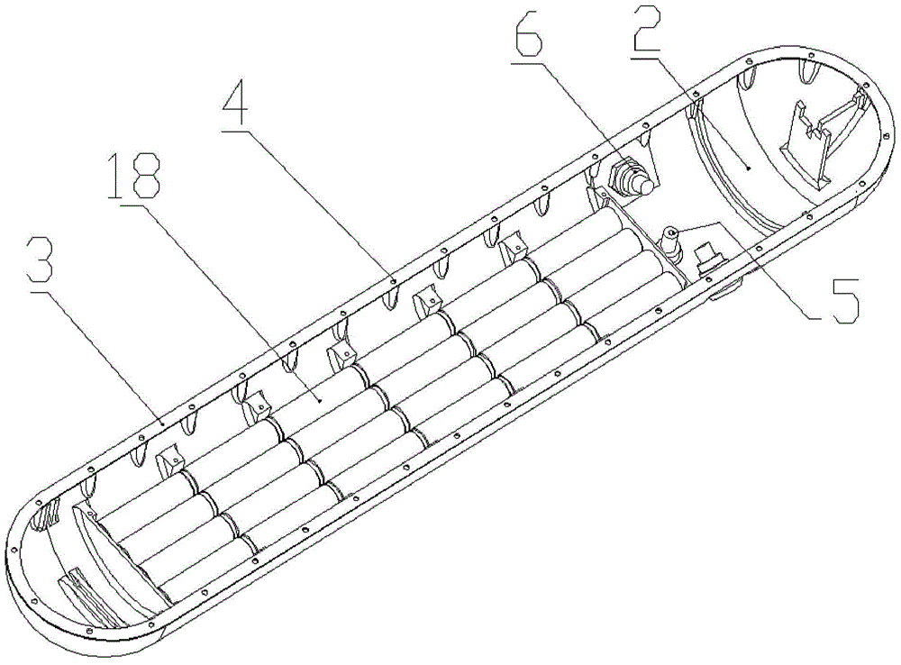
[0024] see figure 1 , figure 2 , image 3 A schematic diagram showing the outline structure of the bionic undulating long-fin underwater propeller, the internal structure of the cavity of the lower cylinder and the internal structure of the cavity of the upper cylinder of the present invention. The bionic undulating long-fin underwater propeller of the present invention includes a lower half cylinder 1, an upper half cylinder 2, a sealing ring 3, a first screw hole 4, a valve core 5, a waterproof plug 6, a plurality of first bevel gears 7, a plurality of Fin ray 8, long fin 9, control circuit board 10, multiple first steering gear 11, multiple layering bars 12, first bearing seat 13, counterweight 14, screw rod 15, sec...
PUM
Abstract
The invention relates to a bionic fluctuating long fin underwater propulsor which comprises an upper half drum, a lower half drum, a seal ring, a screw hole, an inflating valve core, a waterproof plug, a first bevel gear, a plurality of fin strips, a long fin, a control circuit board, a first steering gear, a second steering gear, a pressing strip, a first bearing block, a balancing weight, a screw rod, a screw hole, a battery module and a multichannel first steering gear output structure, wherein the multichannel first steering gear output structure is composed of a long shaft, a fin strip base, a second bearing block, a shaft sleeve, a polytetrafluoroethylene ring, a Glyd ring, a ball bearing and a second bevel gear. The upper half drum, the lower half drum and the seal ring are connected and pressed to form a sealed cavity, the long fin is arranged on the lower portion of a cylindrical cavity, the long fin is provided with the fin strips, and the fin strips are equidistantly distributed on the surface of the long fin. Each fin strip is connected with the first steering gear through the first bevel gear and the second bevel gear to be independently driven, the surface of the long fin is made of a flexible film made of a latex material, and the long fin can be driven by the fin strips to achieve multiple waveforms of sine or other types and have the effect with water to generate stable propulsive force.
Description
technical field [0001] The invention belongs to the technical field of bionic robot fish, and relates to a bionic undulating long-fin underwater propeller, in particular to a bionic undulating long-fin underwater propeller imitating the swimming mode of a swordfish. Background technique [0002] In recent years, autonomous underwater vehicles (AUVs) have been widely used in ocean development, marine research, underwater environmental protection and other fields. Traditional underwater propellers such as propellers will generate a large amount of noise with large bandwidth in the wake, causing serious damage to some underwater ecosystems, and also have disadvantages such as low efficiency and poor maneuverability. After a long period of evolution, fish have evolved various efficient and highly maneuverable propulsion methods. Simulating the propulsion mode of fish, and developing intelligent bionic underwater robots with high performance, high mobility, and little disturbanc...
Claims
Application Information
Patent Timeline
Application Date:The date an application was filed.
Publication Date:The date a patent or application was officially published.
First Publication Date:The earliest publication date of a patent with the same application number.
Issue Date:Publication date of the patent grant document.
PCT Entry Date:The Entry date of PCT National Phase.
Estimated Expiry Date:The statutory expiry date of a patent right according to the Patent Law, and it is the longest term of protection that the patent right can achieve without the termination of the patent right due to other reasons(Term extension factor has been taken into account ).
Invalid Date:Actual expiry date is based on effective date or publication date of legal transaction data of invalid patent.