Surface photovoltage measuring method with combination of modulated light and non-modulated light

A technology of surface photovoltage and non-modulated light, which is applied in measuring devices, material analysis through optical means, instruments, etc., can solve the problems that photoelectric phenomena cannot be detected by surface photovoltage, and achieve the effect of rich interface information and simple operation

Inactive Publication Date: 2015-08-05
JILIN UNIV
View PDF6 Cites 10 Cited by
  • Summary
  • Abstract
  • Description
  • Claims
  • Application Information

AI Technical Summary

Problems solved by technology

[0004] However, there are still many photoelectric phenomena that cannot

Method used


Image

  • Surface photovoltage measuring method with combination of modulated light and non-modulated light
  • Surface photovoltage measuring method with combination of modulated light and non-modulated light
  • Surface photovoltage measuring method with combination of modulated light and non-modulated light

Examples


Embodiment 1

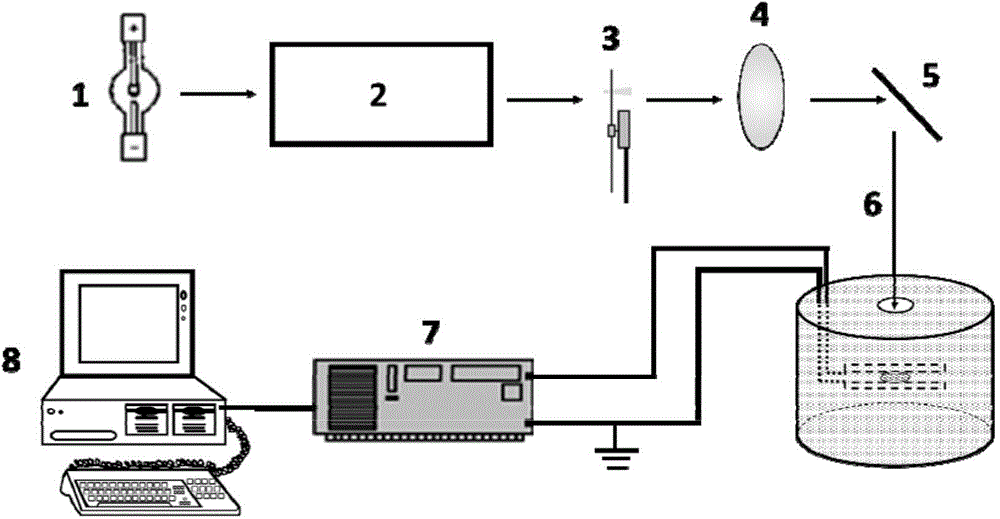
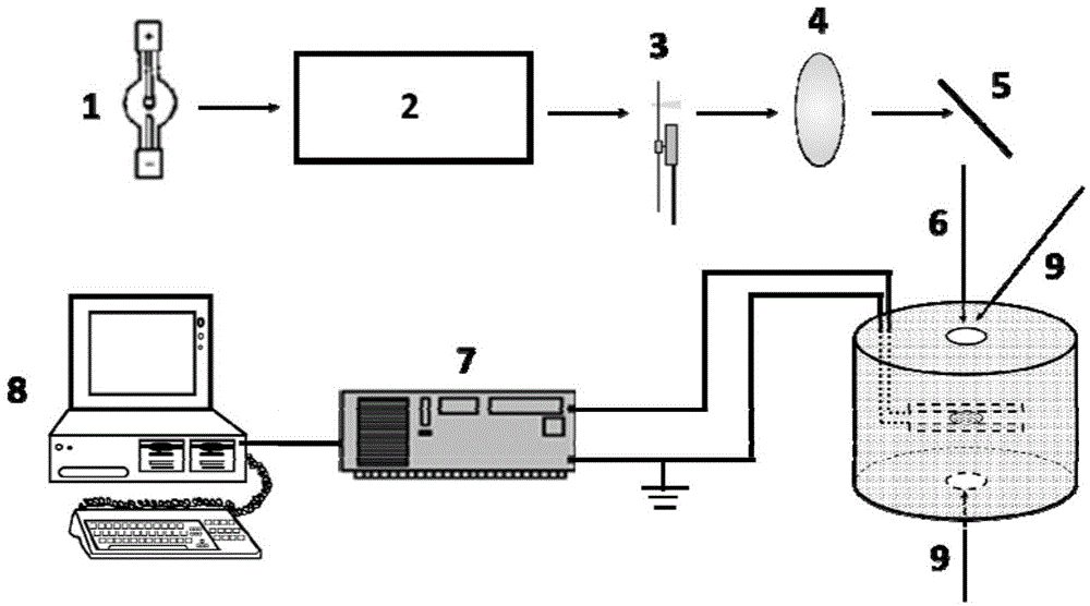
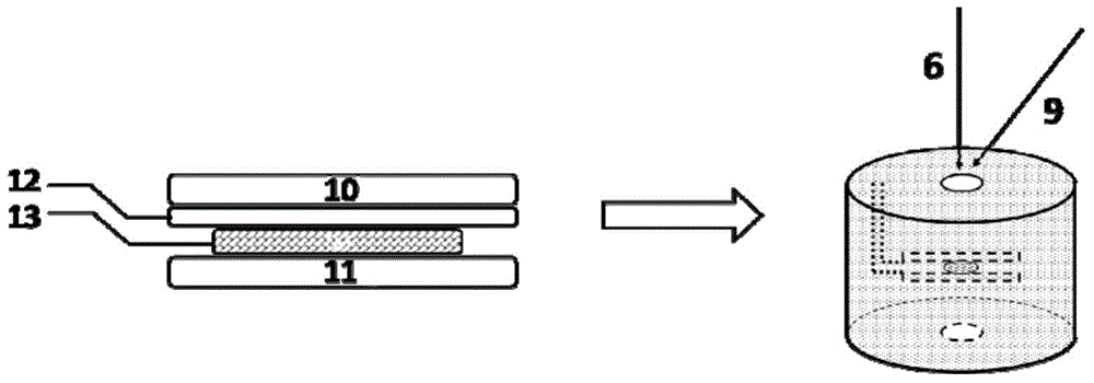
[0037] (1) The measurement sample is cadmium sulfide nanowires synthesized by ethylenediamine hydrothermal method (see Solvothermal Synthesis of CdS Nanowires for Photocatalytic Hydrogen and Electricity Production, The Journal of Physical Chemistry C.2007, 111, 13280-13287 for the synthesis method). Measurement models such as image 3 Shown: Put the cadmium sulfide nanowire on the ITO bottom electrode, cover it with 20μm mica sheet, then cover the ITO upper electrode, put it into the photovoltage sample cell (all steel sample cell), and the upper electrode is connected to the phase lock by the wire in the sample cell The input terminal of the amplifier and the lower electrode are externally grounded through the wire in the sample cell. The sample cell is of all steel structure, which can effectively shield external noise signals.

[0038] (2) Without applying non-modulated light, the surface photovoltage spectrum test results are as follows: Figure 4 As shown, the scanning w...

Embodiment 2

[0042] (1) TiO 2 -Ti-ZnFe 2 o 4 Ternary composite system surface photovoltage test. The sample preparation process is as follows: double-sided TiO was prepared from Ti foil by electrochemical anodization 2 Nanotubes, and then one side is polished to expose the Ti substrate, and continue to use the hang coating method to load a layer of ZnFe 2 o 4 (See Surface photovoltaic phase spectrum for analyzing the photogenerated charge transfer and photocatalytic activity of ZnFe for the synthesis method 2 o 4 –TiO 2 nanotube arrays,Physical Chemistry Chemical Physics.2013,15,14262-14269, the difference is ZnFe 2 o 4 loaded on the polished Ti substrate side).

[0043] (2) Dual photosystem TiO 2 -Ti-ZnFe 2 o 4 Ternary Structure TiO 2 One side surface photovoltage measurement model such as Figure 8 Shown, TiO 2 -Ti-ZnFe 2 o 4 The sample is placed on the bottom electrode of ITO, covered with 20μm mica sheet, then covered with the upper electrode of ITO, put into the photo...


PUM


Abstract

The invention discloses a surface photovoltage measuring method with a combination of modulated light and non-modulated light and belongs to the technical field of semiconductor photovoltage measurement. The surface photovoltage measuring method comprises the following steps: putting a sample to be measured on an ITO conductive glass bottom electrode, covering the sample to be measured with a mica sheet with the thickness being 10-40 microns, and covering the mica sheet with an upper electrode; turning on a light source, enabling the modulated light and the non-modulated light to irradiate the sample to be measured simultaneously, amplifying a photovoltage signal generated between the bottom electrode and the upper electrode of the sample to be measured by a phase-locking amplifier, inputting the signal into a computer, recording the intensity value of the photovoltage signal of the sample to be measured by the computer, and further realizing the measurement for the surface photovoltage of the sample to be measured. The surface photovoltage measuring method disclosed by the invention has the advantages that by utilization of a detection result, the capturing action of a semiconductor surface state on photogenerated charge, the dynamic migration of bulk-phase photogenerated charge and the migration behavior of photogenerated charge of an all-solid-state Z-shaped semiconductor compound system can be directly discussed.

Description

technical field [0001] The invention belongs to the technical field of new energy development, and specifically relates to a method for measuring the surface photovoltage of a novel photoelectric functional material combining modulated light and non-modulated light. The photoelectric charge transmission characteristics of the material can be characterized by measuring the surface photovoltage. Background technique [0002] The research and preparation of new optoelectronic functional materials play a vital role in solving energy and environmental problems, and the detection of optoelectronic properties of materials plays a vital role in the research and development of new optoelectronic materials. Surface photovoltage spectroscopy is a very promising detection method for photoelectric performance, which has the characteristics of high sensitivity, simple operation, and non-destructive samples, so it is widely used in the research of analyzing the photogenerated charge behavio...

Claims


Application Information

Patent Timeline
IPC IPC(8): G01N21/17
Inventor 谢腾峰李硕王德军林艳红
Owner JILIN UNIV
Why Eureka
Try Eureka