Structure of self-mode-locked pulses in compressed fiber lasers

A fiber laser, self-mode-locking technology, applied to the structure/shape of lasers, active media, laser components, etc., can solve problems such as relatively expensive, increased laser weight and volume, and system complexity and cost

Active Publication Date: 2017-10-10
YANGZHOU UNIV
View PDF5 Cites 0 Cited by
  • Summary
  • Abstract
  • Description
  • Claims
  • Application Information

AI Technical Summary

Problems solved by technology

[0003] The present invention aims at the complexity and cost of the system existing in the above-mentioned existing method for reducing the self-mode-locking pulse of the fiber laser or the shortage of increasing the weight and volume of the laser, and provides a simple structure, easy operation, wide application and relatively high performance. A cost-effective structure for compressing self-mode-locked pulses of fiber lasers

Method used


Image

  • Structure of self-mode-locked pulses in compressed fiber lasers
  • Structure of self-mode-locked pulses in compressed fiber lasers
  • Structure of self-mode-locked pulses in compressed fiber lasers

Examples


Embodiment approach 1

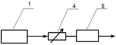
[0016] Implementation mode one: if figure 1 As shown, the present embodiment is a single-stage fiber amplifier processing stage, and the fiber laser output end 1-1 of the fiber laser 1 is connected to the adjustable optical attenuator input end 4-1 of the adjustable optical attenuator 4 in the processing stage, which can be The output port 4-2 of the dimming attenuator is connected to the fiber amplifier input port 5-1 of the fiber amplifier 5, and the fiber amplifier output port 5-2 is connected to the input port of the operating system; 2 Connect the adjustable optical attenuator to avoid the measurement equipment being damaged by high-power laser (use an optical power meter to measure the optical power value), the output end of the adjustable optical attenuator is connected to the input end of the optical receiver, and the electrical output port of the optical receiver is connected to the oscilloscope . Adjust the adjustable optical attenuator 4 before the fiber amplifier ...

Embodiment approach 2

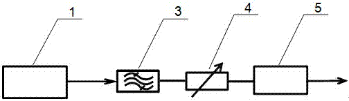
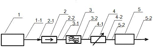
[0017] Implementation mode two: if figure 2 , 3 As shown, the present embodiment is an improvement of the single-stage fiber amplifier processing stage, the fiber laser output end 1-1 of the fiber laser 1 is connected to the optical isolator input end 2-1 of the optical isolator 2 in the processing stage, and the optical isolator output The end 2-2 is connected to the optical bandpass filter input end 3-1 of the optical bandpass filter 3, and the optical bandpass filter output end 3-2 is connected to the adjustable optical attenuator input end of the adjustable optical attenuator 4 4-1, the output port 4-2 of the adjustable optical attenuator is connected to the fiber amplifier input port 5-1 of the fiber amplifier 5, and the fiber amplifier output port 5-2 is connected to the input port of the operating system; The output terminal 5-2 of the amplifier is connected to the adjustable optical attenuator to prevent the measuring equipment from being damaged by high-power laser ...

Embodiment approach 3

[0018] Implementation mode three: if image 3 , 4 As shown, the present embodiment is a series connection of multi-stage fiber amplifier processing stages, the fiber laser output end 1-1 of the fiber laser 1 is connected to the first fiber amplifier processing stage 6, and the output end of the first fiber amplifier processing stage 6 is connected to The input end of the second optical fiber amplifier processing stage 7, and so on, the output end of the Nth optical fiber amplifier processing stage 8 is connected to the input end of the application system, and the structure of each processing stage can be combined with figure 1 or figure 2 or image 3 The same as shown; when the measurement equipment needs to be connected, the output port 5-2 of the optical fiber amplifier in the last stage is connected to an adjustable optical attenuator to avoid the measurement equipment being damaged by high-power laser (use an optical power meter to measure the optical power value), adju...


PUM


Abstract

The invention relates to a structure for compressing the self-mode-locked pulse of a fiber laser, which belongs to the technical field of fiber lasers and fiber amplifiers. The main feature is that the fiber amplifier is used to improve the output performance of the fiber laser. The processing stage composed of fiber amplifier and adjustable optical attenuator, the output of the fiber laser working in continuous mode with self-mode-locking phenomenon is shown as a periodic optical pulse superimposed on the stable DC component, and the intensity of the optical pulse is significantly greater than that of the DC component. Intensity, the present invention can use all the materials and devices that can be purchased on the market to build a processing system, so as to achieve high cost performance. Fiber Laser Performance.

Description

technical field [0001] The invention relates to a structure for compressing self-mode-locked pulses of fiber lasers, which uses fiber amplifiers to improve the output performance of fiber lasers, such as compressing the self-mode-locked pulses of fiber lasers, thereby realizing high-performance continuous fiber lasers, belonging to fiber lasers and Optical fiber amplifier technology field. Background technique [0002] Fiber lasers working in continuous mode are being accepted by more and more applications due to their small weight and volume, high beam weight, stable and reliable performance, etc. However, continuous fiber lasers often produce multiple longitudinal modes because the optical cavity is excited by a disturbance factor or noise. These longitudinal mode pulses whose repetition frequency is determined by the length of the optical cavity will be strengthened because they pass through the gain medium multiple times. In the laser The output of the optical fiber is ...

Claims


Application Information

Patent Timeline
Patent Type & Authority Patents(China)
IPC IPC(8): H01S3/098H01S3/067
Inventor 沈明亚乔鑫
Owner YANGZHOU UNIV
Why Eureka
Try Eureka