
Bridge stay cable force online detection method and system based on fiber sensing

A technology of optical fiber sensing and detection system, which is applied in the direction of tension measurement and the measurement of the change force of the optical properties of the material when it is stressed, and can solve the problems of poor reliability of identification methods, poor stability of optical fiber sensors, and poor system reusability To achieve the effect of improving stability and anti-interference ability, narrowing the frequency identification interval, and improving detection ability

Inactive Publication Date: 2015-08-19
WUHAN UNIV OF TECH
View PDF4 Cites 10 Cited by
  • Summary
  • Abstract
  • Description
  • Claims
  • Application Information

AI Technical Summary

Problems solved by technology

[0006] (1) The stability of the fiber optic sensor is poor
The main reason is that the reflection spectrum of the sensor element FBG used is narrow. Due to the influence of the installation process and the change of ambient temperature, the probability of double grating matching failure is high. In addition, the design of the double cantilever beam structure is also one of the reasons for the failure of the sensor.
[0007] (2) Single-point measurement, the system has poor multiplexing ability, it is difficult to form a large-scale sensor network, and distributed measurement cannot be realized
[0008] (3) The reliability of the identification method is poor
[0009] For the above-mentioned problems, there are no relevant reports of solutions so far

Method used


Image

  • Bridge stay cable force online detection method and system based on fiber sensing
  • Bridge stay cable force online detection method and system based on fiber sensing
  • Bridge stay cable force online detection method and system based on fiber sensing

Examples


Embodiment Construction

[0023] The present invention will be further described below in conjunction with specific examples and accompanying drawings.

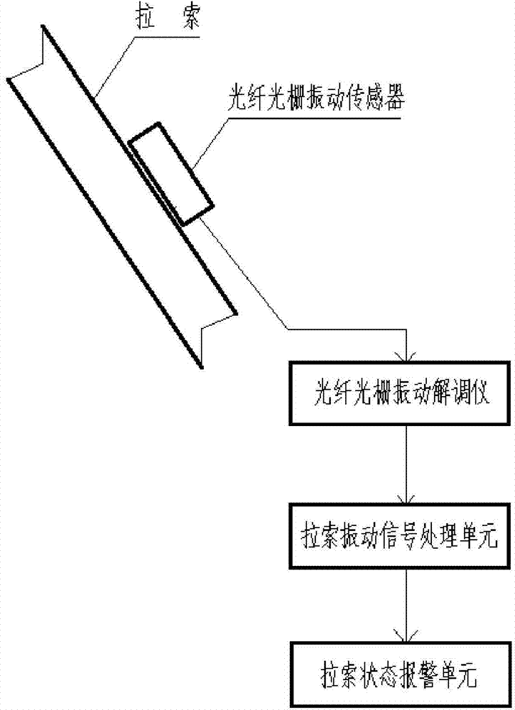
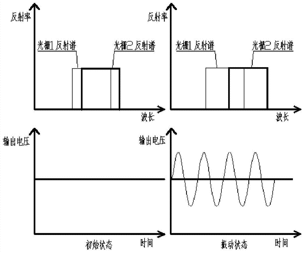
[0024] An online detection system for bridge cable force based on optical fiber sensing, such as figure 1 As shown, it includes a fiber grating vibration sensor group, a fiber grating vibration demodulator, and a cable vibration signal processing unit connected in sequence. Preferably, an alarm unit connected to the cable vibration signal processing unit can also be added to analyze and judge the state of the cable Is it safe. The fiber grating vibration sensor group includes several fiber grating vibration sensors connected in series on the same optical fiber, each fiber grating vibration sensor such as figure 2 As shown, it includes a cantilever beam 5 (single cantilever beam structure) arranged on the bridge cable, the end of the cantilever beam 5 is connected with a mass block 4, and a pair of chirped gratings are symmetrically arranged on the u...


PUM


Abstract

The invention provides a bridge stay cable force online detection method and system based on fiber sensing. The system comprises a fiber grating vibration sensor group, a fiber grating vibration demodulation instrument and a stay cable vibration signal processing unit. The fiber grating vibration sensor group comprises a plurality of fiber grating vibration sensors connected in series with the same fiber, each fiber grating vibration sensor is designed based on a cantilever structure and a double-raster coupling method, and chirp rasters are used to replace Bragg rasters, such that the detection scope of the sensors is enlarged, the stability and the anti-interference capability of the sensors are improved, and at the same time, the manufacturing difficulty of the sensors is reduced. The fiber grating vibration demodulation instrument is based on an edge filtering demodulation principle and employs a wavelength division multiplexing technology to realize distributed measurement of a stay cable force, and multiple fiber grating vibration sensors can be multiplexed in one fiber signal, such that the detection capability of the system is improved, the distributed measurement of the stay cable force is made possible, and a more reliable technical means is provided for online detection of a wide-span bridge stay cable.

Description

technical field [0001] The invention belongs to the technical field of optical fiber sensing and detection, and in particular relates to an online detection method and system for cable force of bridge cables based on optical fiber sensing. Background technique [0002] Cables are important stress-bearing components of cable-type (cable-stayed cables, suspension cables, etc.) bridges, and their stress state is one of the important indicators for evaluating the safety of bridge structures. Therefore, it is of great significance to study the cable force detection method of the cable, especially the online detection method, to evaluate the health status of the bridge. [0003] At present, there are many methods for detecting cable force of stay cables, such as oil pressure gauge method, magnetic flux method, force measuring ring method, frequency method and so on. But for the bridges that have been built, the frequency method is almost the only choice. The so-called frequency ...

Claims


Application Information

Patent Timeline
Patent Type & Authority Applications(China)
IPC IPC(8): G01L5/04G01L1/24
Inventor 南秋明李盛岳丽娜杨燕张翠
Owner WUHAN UNIV OF TECH
Learn More