Ultrasonic vibration magneto-rheological brush polishing machine for non-magnetic screws

A technology of ultrasonic vibration and magnetorheological brush, which is applied in the field of non-magnetic screw ultrasonic vibration magnetorheological brush polishing machine, can solve the problem of high surface roughness and achieve the effect of high surface roughness

Inactive Publication Date: 2015-08-26
ZHEJIANG NORMAL UNIVERSITY
View PDF7 Cites 8 Cited by
  • Summary
  • Abstract
  • Description
  • Claims
  • Application Information

AI Technical Summary

Problems solved by technology

[0003] The purpose of the present invention is to provide a non-magnetic screw ultrasonic vibration magneto-rheological brush polishing machine,

Method used


Image

  • Ultrasonic vibration magneto-rheological brush polishing machine for non-magnetic screws
  • Ultrasonic vibration magneto-rheological brush polishing machine for non-magnetic screws
  • Ultrasonic vibration magneto-rheological brush polishing machine for non-magnetic screws

Examples


Embodiment 1

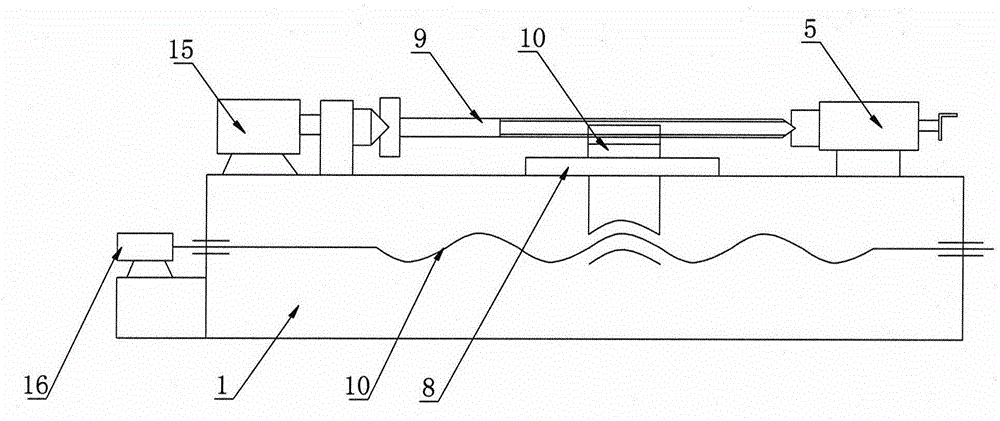
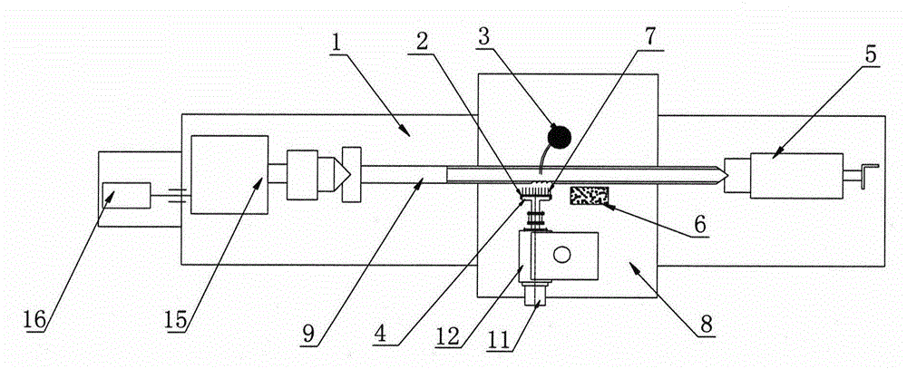
[0017] refer to figure 1 , figure 2 It is an embodiment of the non-magnetic screw ultrasonic vibration magnetorheological brush polishing machine of the present invention. The non-magnetic screw ultrasonic vibration magnetorheological brush polishing machine includes a lathe body 1, a polishing liquid 13 containing magnetorheological fluid, and is fixed on the lathe The ultrasonic magnetic polishing assembly on the carriage 8 and the pump body 3 that sprays the polishing liquid 13 on the ultrasonic magnetic polishing assembly;

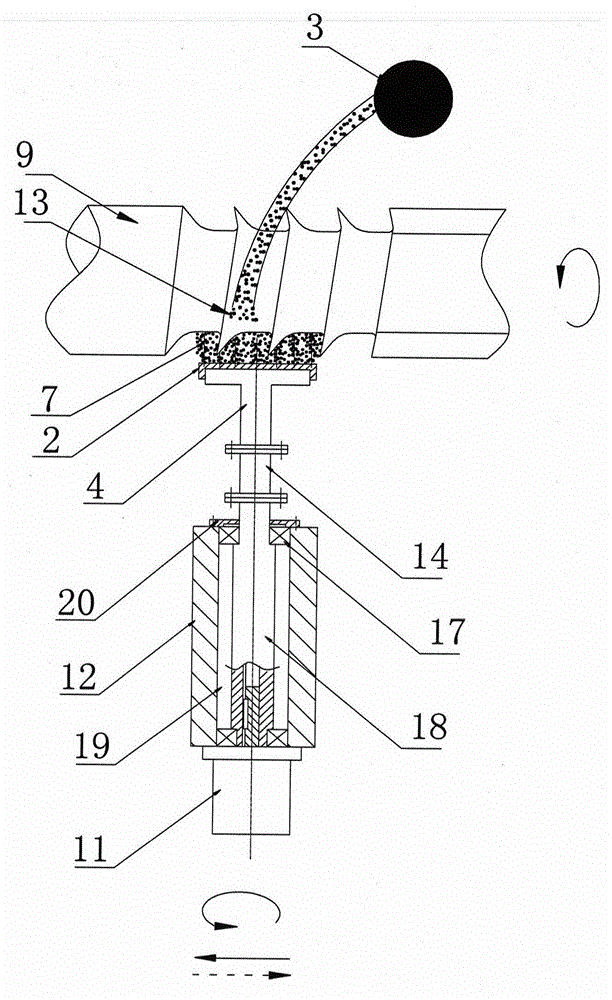
[0018] Such as image 3 As shown, the ultrasonic magnetic polishing assembly includes a clamping handle 12 fixed on the lathe carriage 8, a first connecting shaft 18 arranged in the clamping handle 12 for rotation, and a device for driving the first connecting shaft 18 to rotate on the lathe carriage 8. The rotation motor, the ultrasonic vibrator 14 fixedly connected to the front end of the first connecting shaft 18, and the brush plate 2 fixedly co...

Embodiment 2

[0024] refer to Figure 4 , the difference from Embodiment 1 is that the structure of the ultrasonic magnetic polishing assembly is different, and the ultrasonic magnetic polishing assembly includes a clamp handle 12 fixed on the lathe carriage 8, an ultrasonic vibrator 14 fixed on the clamp handle 12, and an ultrasonic vibrator 14 The connected wheel brush holder 23, the second connection shaft 21 arranged on the wheel brush holder 23, the magnetic field generator sleeved on the second connection shaft 21, the brush plate 2 arranged on the outer wall of the magnetic field generator 4, the The magnetic conduction brush 7 is fixed on the brush plate 2 .

[0025] The wheel brush holder 23 includes a connecting portion 22 fixedly connected with the clamp handle 12 and a fixed portion 24 fixed at the front end of the connecting portion 22, the second connecting shaft 21 is erected on the fixing portion 24, and the magnetic field generator 4 is rotationally connected with the seco...


PUM


Abstract

The invention discloses an ultrasonic vibration magneto-rheological brush polishing machine for non-magnetic screws. The polishing machine comprises a lathe body, polishing fluid with magneto-rheological fluid, an ultrasonic magnetic polishing assembly and a pump body for spraying the polishing fluid. The ultrasonic magnetic polishing assembly comprises a clamping handle, a first connecting shaft arranged in the clamping handle in a rotating mode, a motor for driving the first connecting shaft to rotate, an ultrasonic vibrator fixedly connected to the first connecting shaft, and a brush plate fixedly connected to the ultrasonic vibrator. Magnetic conduction brushes are arranged on the brush plate. A magnetic field generator is fixed to the brush plate. The ultrasonic magnetic polishing assembly can also adopt an ultrasonic vibrator fixed to the clamping handle, a wheel brush rack connected with the ultrasonic vibrator, a second connecting shaft arranged on the wheel brush rack, a magnetic field generator arranged on the second connecting shaft in a sleeving mode, and a brush plate arranged on the outer wall of the magnetic field generator. The polishing machine has the advantages that by means of an ultrasonic generator and a magnetic conduction brush plate, extremely-high surface roughness can be obtained, and elements can be ground in all directions without dead corners.

Description

technical field [0001] The invention relates to a non-magnetic screw ultrasonic vibration magnetorheological brush polishing machine. Background technique [0002] At present, non-magnetic screws such as medical intramedullary nails and bone screws are mostly made of titanium alloy materials. The main problem of titanium alloy implant materials is corrosion. On the one hand, corrosion causes corrosion products to enter the human body, causing serious physiological hazards. Such as tissue poisoning, cell aberration, etc.; on the other hand, it causes failure behaviors such as loosening and early fracture of implanted prostheses. The corrosion resistance of titanium alloy decreases with the increase of its surface roughness, among which smooth surface and microscopically rough surface have good corrosion resistance and low ion release rate. Therefore, it is particularly necessary to carry out proper surface finishing treatment on medical titanium alloy implants. Contents of...

Claims


Application Information

Patent Timeline
IPC IPC(8): B24B1/00B24B1/04
CPCB24B1/005B24B1/04
Inventor 王鸿云胡永举刘卫东张忠华孟国连毕成
Owner ZHEJIANG NORMAL UNIVERSITY
Why Eureka
Try Eureka