
Oil drain plug and socket

A technology of plugs and sockets, which is applied in the direction of oil pans, machines/engines, mechanical equipment, etc., can solve the problems of complex manufacturing of plastic oil pans, increased costs and component rotation time, etc., to achieve reliable oil storage systems and reduce meshing The probability of loosening and the effect of making it simple

Inactive Publication Date: 2015-08-26
GM GLOBAL TECH OPERATIONS LLC
View PDF6 Cites 5 Cited by
  • Summary
  • Abstract
  • Description
  • Claims
  • Application Information

AI Technical Summary

Problems solved by technology

[0007] Taken together, it is clear that metal inserts and press-in gaskets complicate the manufacture of plastic oil sumps, thus increasing cost and turnaround time for components

Method used


Image

  • Oil drain plug and socket
  • Oil drain plug and socket
  • Oil drain plug and socket

Examples


Embodiment Construction

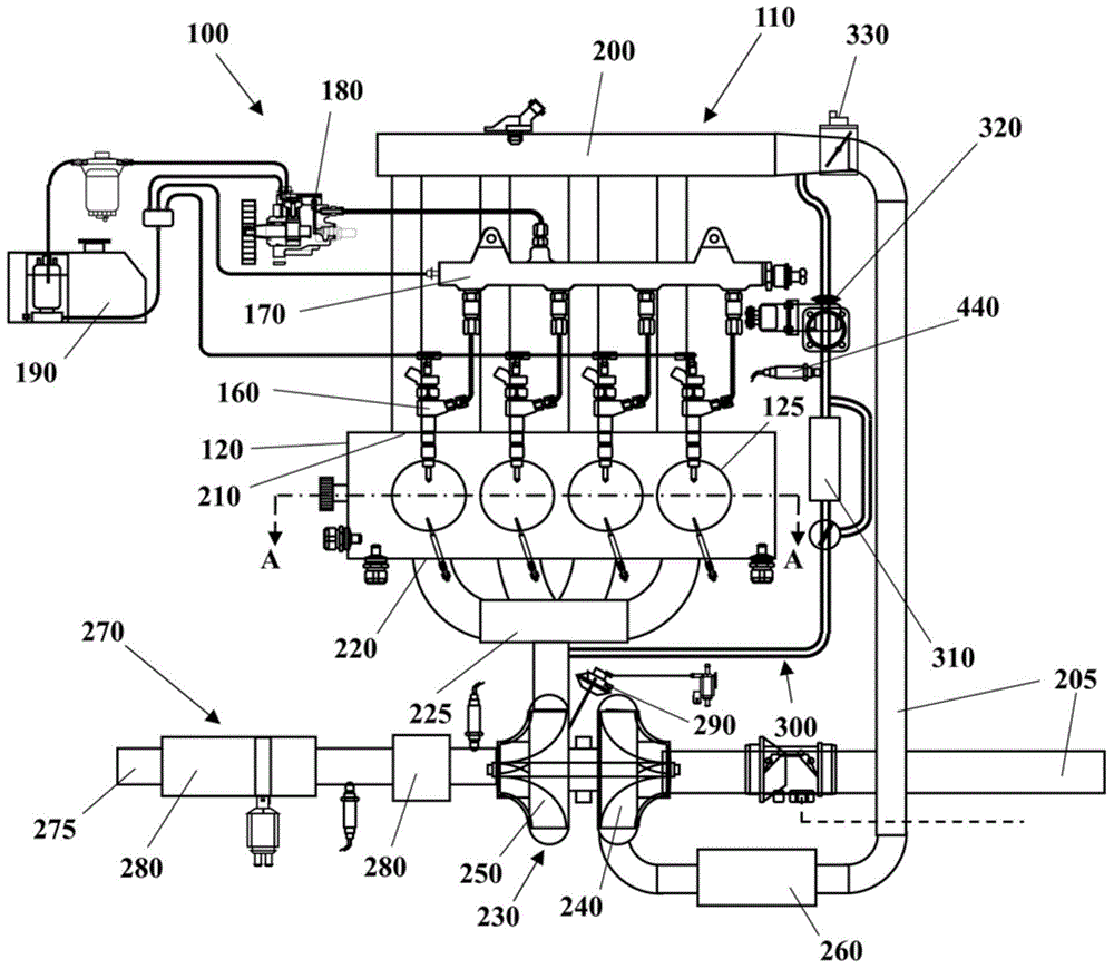
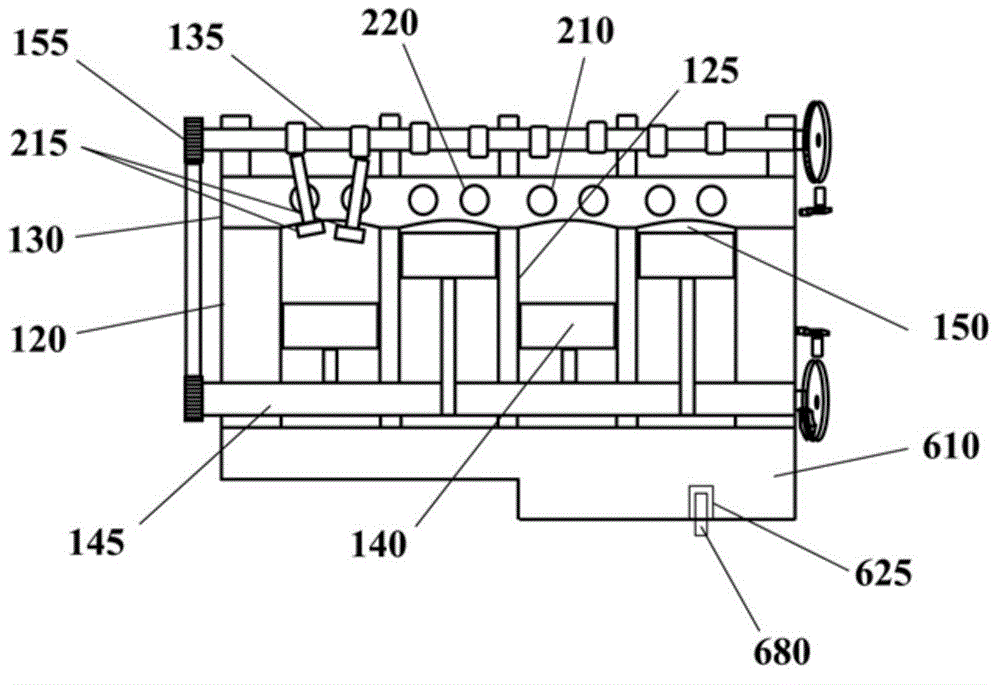
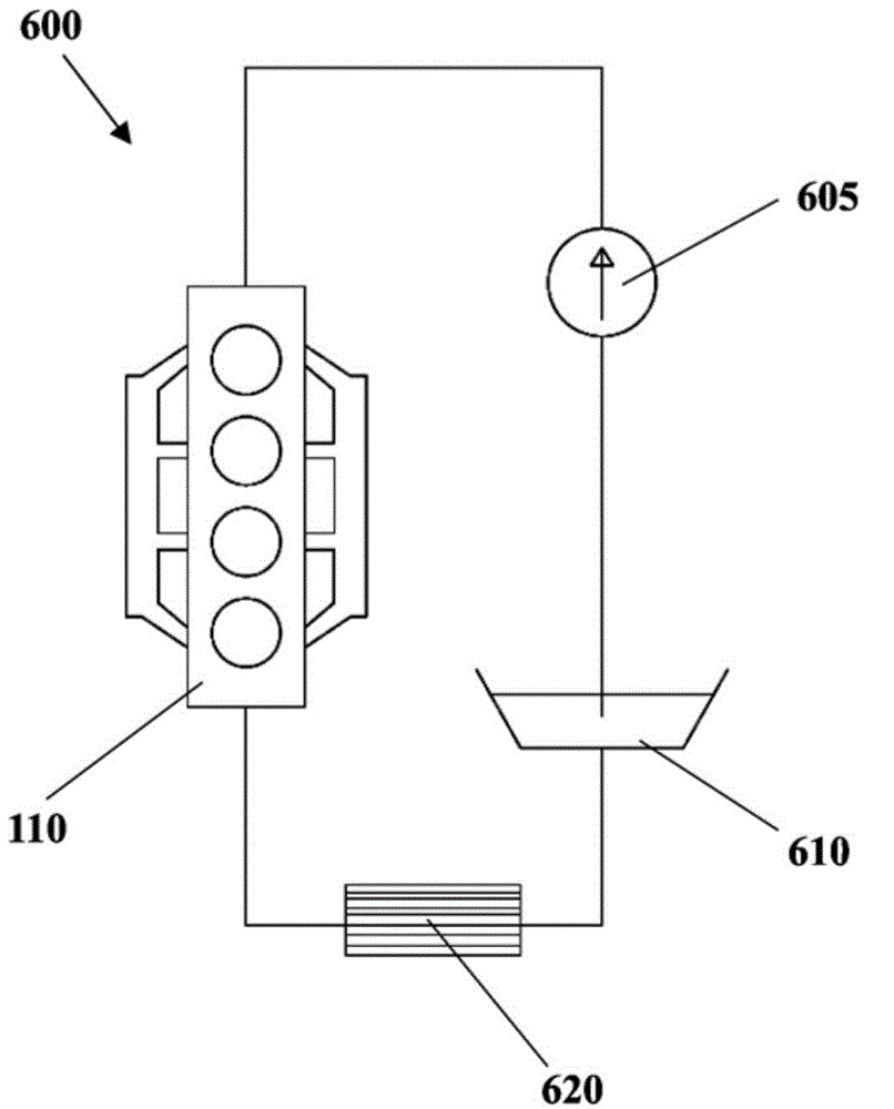
[0058] Some embodiments may include such as figure 1 and 2 The illustrated automotive system 100 includes an internal combustion engine (ICE) 110 having an engine block 120 defining at least one cylinder 125 having a piston 140 for rotating a crankshaft 145 . Cylinder head 130 cooperates with piston 140 to define combustion chamber 150 . A fuel and air mixture (not shown) is input into combustion chamber 150 and ignited, producing hot expanding exhaust gases causing reciprocating motion of piston 140 . Fuel is provided through at least one fuel injector 160 and air is provided through at least one air intake 210 . Fuel is supplied to fuel injector 160 at high pressure from fuel rail 170 which is in fluid communication with high pressure fuel pump 180 to increase the pressure of fuel from fuel source 190 . Each cylinder 125 has at least two nozzles 215 driven by a camshaft 135 that rotates simultaneously with the crankshaft 145 . Nozzle 215 selectively allows air to enter c...


PUM


Abstract

An oil drain plug is disclosed for cooperating with a socket in an oil sump. The plug includes a main body, an eccentric pin protruding from the main body, and an enlarged tip on an end of the eccentric pin. The socket includes a cup-shaped cavity having a lateral wall open at one end, closed at the opposite end by a bottom wall and including an internal surface for mating with the main body of the plug. The bottom wall includes an external surface facing outside the cavity, a through hole such that the enlarged tip of the plug extends beyond the external surface, and a slot departing from the through hole towards a distal end along an arched path centered in the axis and having a smaller width than the through hole for preventing the enlarged tip of the plug from passing through it.

Description

technical field [0001] The invention relates to an oil drain plug and a socket cooperating with the plug. In particular, the invention relates to an oil drain plug and socket for an oil sump of an internal combustion engine. Background technique [0002] It is known that internal combustion engines generally comprise an engine block defining a number of cylinders. Each cylinder is fitted with a piston coupled to the crankshaft and cooperates with the cylinder head to define a combustion chamber. A fuel and air mixture is cyclically placed in the combustion chamber and ignited, causing thermally expanding exhaust gases to cause reciprocation of the pistons and rotation of the crankshaft. [0003] During operation, the rotating and sliding parts of the components of the internal combustion engine are lubricated by lubrication circuits. The lubrication circuit usually consists of an oil sump fixed on the bottom of the engine block and an oil pump which draws, for example, en...

Claims


Application Information

Patent Timeline
IPC IPC(8): F01M11/04F16J15/06
CPCF01M11/0004F01M2011/0416F01M11/0408F16J15/06F01P11/0276
Inventor G.坎迪拉G.埃斯波西托L.阿加陶
Owner GM GLOBAL TECH OPERATIONS LLC
Learn More