Optical fiber end head pressing device with simple structure

A technology with simple structure and optical fiber, which is applied in the direction of light guide, optics, optical components, etc., can solve the problems of inconvenient small-scale processing and use, complex structure, etc., and achieve the effect of simple and practical principle, easy operation, and improved tensile strength

Inactive Publication Date: 2015-08-26
CHENGDU MAKEMODE COMM TECH
View PDF5 Cites 2 Cited by
  • Summary
  • Abstract
  • Description
  • Claims
  • Application Information

AI Technical Summary

Problems solved by technology

When fixing the connector, a cylindrical crimping ring is used to further fix the protective sleeve of the optical fiber and the connector. However, the existing pressing device has a complicated structure and is not convenient for small-scale processing and use.

Method used


Image

  • Optical fiber end head pressing device with simple structure

Examples


Embodiment 1

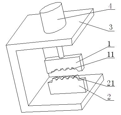
[0018] like figure 1 The illustrated optical fiber end pressing device with simple structure includes an operating table 3, a lower pressure-bearing block 2 fixed on the operating table 3, and an upper pressing block 1 located above the lower pressure-bearing block. The operating table 3 A lifting control device 4 for controlling the up and down movement of the upper pressing block 1 is arranged on the top, the lower pressure bearing block 2 is provided with an optical fiber placement groove 21, and the upper pressing block 1 is provided with an optical fiber placement groove 21 corresponding to the optical fiber The pressing groove 11, when the optical fiber pressing groove 11 is pressed on the optical fiber placement groove 21, both of them form a regular hexagonal pressing groove.

[0019] During operation, the connecting ring is sleeved on the connection between the optical fiber and the connector, the connecting ring is placed in the optical fiber placement groove 21, and...

Embodiment 2

[0021] like figure 1 The optical fiber end pressing device with a simple structure is shown. In order to facilitate the operation of the lifting control device, this embodiment is optimized on the basis of the above-mentioned embodiment, that is, the lifting control device 4 is a hydraulic cylinder or a pneumatic cylinder. cylinder.

[0022] The upper pressing block 1 is fixed on the piston rod of the lifting control device 4 .

Embodiment 3

[0024] like figure 1 In the illustrated optical fiber end pressing device with a simple structure, in order to improve the pressing efficiency of the optical fiber end, this embodiment is optimized on the basis of the above-mentioned embodiment, that is, the lower pressure bearing block 2 is provided with multiple A fiber placement groove 21.

[0025] In order to facilitate the manufacture of the optical fiber placement groove and the optical fiber pressing groove, the cross section of the optical fiber placement groove 21 is an isosceles trapezoid.


PUM


Abstract

The invention discloses an optical fiber end head pressing device with a simple structure. The optical fiber end head pressing device comprises an operation table, a lower pressure bearing block which is fixed on the operation table and an upper pressuring block which is arranged above the lower pressure bearing block. The operation table is provided with an elevating control device which controls upward and downward movement of the upper pressing block. The lower pressure bearing block is provided with optical fiber placing slots. The positions, which are corresponding to the optical fiber placing slots, of the upper pressing block are provided with optical fiber pressing slots. When the optical fiber pressing slots press the optical fiber placing slots, regular hexagonal pressing slots are formed by the optical fiber pressing slots and the optical fiber placing slots. The optical fiber end head pressing device is simple in structure and suitable for being applied to miniature processing.

Description

technical field [0001] The invention relates to the field of optical fiber processing devices, and more specifically relates to an optical fiber end pressing device with a simple structure. Background technique [0002] The optical fiber cylindrical dielectric waveguide is composed of three parts: the core and the cladding coating layer. Generally, the core diameters of single-mode and multi-mode optical fibers are 5-15 μm and 40-100 μm, and the cladding diameters are about 125-600 μm. After processing the fiber end, the ideal state of the fiber end is a smooth surface. In actual situations, the optical fiber end is often not in an ideal state, such as unsatisfactory polishing, scratches, surface or edge damage, etc., which will complicate the end situation. When the optical fiber is installed by pulling wires, there are certain requirements not only for the tensile strength of the optical fiber itself, but also for the tensile strength of the fiber end. In order to facil...

Claims


Application Information

Patent Timeline
Patent Type & Authority Applications(China)
IPC IPC(8): G02B6/36
CPCG02B6/3624
Inventor 蔡义炜钱兴容曾应全
Owner CHENGDU MAKEMODE COMM TECH
Why Eureka
Try Eureka