Microbubble generator for reinforced hydrogenation technology

A micro-bubble generator and process technology, applied in chemical instruments and methods, petroleum industry, mixers, etc., can solve problems such as no disclosure, and achieve the effects of simple structure, enhanced gas-liquid mixing, and good mixing effect

Active Publication Date: 2015-09-02
LUOYANG PETROCHEMICAL ENG CORP SINOPEC +1
View PDF5 Cites 32 Cited by
  • Summary
  • Abstract
  • Description
  • Claims
  • Application Information

AI Technical Summary

Problems solved by technology

[0008] At present, the microbubble technology is mainly used in the sewage treatment industry. The specific structure of the microbubble generator used in the hydrogenation process ha

Method used


Image

  • Microbubble generator for reinforced hydrogenation technology

Examples


Embodiment Construction

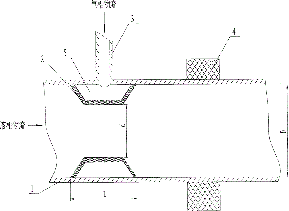
[0024] The microbubble generator for intensified hydrogenation process of the present invention will be further described below in conjunction with the accompanying drawings.

[0025] The structure of the microbubble generator of the present invention is as figure 1 As shown, it is mainly composed of a main body tube 1, a venturi tube 2, an air intake tube 3 and an ultrasonic generator 4; An independent annular air intake space 5 is formed between the inner wall of the main pipe 1, the air intake pipe 3 is welded on the outer wall of the main pipe 1 and communicates with the annular air intake space 5, and the Venturi tube 2 is made of microporous material , the air intake pipe 3, the annular air intake space 5 and the micropores of the Venturi tube 2 together form a gas channel, and the inner wall of the Venturi tube 2 and the inner wall of the main tube 1 jointly form a gas-liquid channel; the ultrasonic generator 4 is installed on the main tube 1 On the outer wall and loca...


PUM


Abstract

The invention discloses a microbubble generator for a reinforced hydrogenation technology. The microbubble generator mainly comprises a main pipe, a Venturi tube, an air inlet pipe and an ultrasonic generator. The Venturi tube and the main pipe are coaxially arranged and are welded to the inner wall of the main pipe. A detached annular air-inlet space is formed between the outer wall of the Venturi tube and the inner wall of the main pipe. The air inlet pipe is welded to the outer wall of the main pipe and is communicated with the annular air-inlet space. The Venturi tube is prepared from a microporous material. The air inlet pipe, the annular air-inlet space and micropores of the Venturi tube form gas channels. The inner wall of the Venturi tube and the inner wall of the main pipe form a gas-liquid channel. The ultrasonic generator is installed on the outer wall of the main pipe and is located in the downstream of the Venturi tube. The microbubble generator can improve hydrogenation efficiency and realize deep and high efficiency hydrotreatment or hydrocracking of an oil product.

Description

technical field [0001] The invention relates to a bubble generator, in particular to a microbubble generator for strengthening hydrogenation process. Background technique [0002] Hydrotreating and cracking of various oil products is the most reasonable and effective method to maximize the utilization of crude oil and upgrade oil products. The existing oil hydrogenation technology is divided into fixed bed hydrogenation, moving bed hydrogenation, suspension bed hydrogenation and ebullated bed hydrogenation, etc. Various oil hydrogenation processes have different bed types, and the hydrodynamic properties of the gas-liquid flow are quite different, but the chemical reaction between the oil and hydrogen occurs under the action of the catalyst. As long as the hydrogen dissolves more before the raw oil enters the reactor, supersaturated dissolution can be achieved, the hydrogen-oil ratio in the operation of the device can be reduced, and the reaction efficiency can be improved ...

Claims


Application Information

Patent Timeline
IPC IPC(8): B01F13/10B01F3/04C10G45/00C10G47/00C10G49/00
Inventor 蔡连波陈强赵晓青盛维武
Owner LUOYANG PETROCHEMICAL ENG CORP SINOPEC
Why Eureka
Try Eureka