Laser machining system for forming of pointed end of microprobe

A laser processing and micro-probe technology, applied in laser welding equipment, metal processing equipment, manufacturing tools, etc., can solve the influence of the probe tip, the size of the heating area cannot be adjusted according to the processing requirements, and the tip forming consistency and repeatability are poor, etc. problems, to achieve precise control of machining power and action time, easy machining power and action time, good forming consistency and repeatability

Inactive Publication Date: 2015-09-02
SICHUAN UNIV
View PDF10 Cites 14 Cited by
  • Summary
  • Abstract
  • Description
  • Claims
  • Application Information

AI Technical Summary

Problems solved by technology

The main problems of this processing method are: 1. The flame space distribution is relatively large, which is not suitable for precise processing of small parts
2. The flame temperature field generated by combustion is easily affected by external influences such as airflow and humidity, and the heating time cannot be precisely controlled, resulting in poor consistency and repeatability of tip molding
3. The combustion of fuel will introduce other oxides to attach to the spherical tip of the probe, which will affect the tip of the probe
But in terms of its own characteristics, there are still the following defects: 1. The heating area is relatively large, which is not suitable for precise processing of small parts
2. During the heating process, the heating material is easy to be pulverized and cracked, releasing toxic substances; 3. The heating speed of the heating material is slow and requires a large current, which requires high hardware circuits
The main defects of the electrode discharge machining method are: 1. Although the heating area is smaller than the previous ones, its size cannot be adjusted according to the processing requirements, and the flexibility and versatility are poor.
2. There are defects such as arc craters and bubbles on the surface of the processed spherical tip
3. In order to prevent the processed material and the discharge electrode from reacting with oxygen during processing, a protective gas needs to be introduced, so the structure is complex and difficult to operate

Method used


Image

  • Laser machining system for forming of pointed end of microprobe
  • Laser machining system for forming of pointed end of microprobe

Examples


Embodiment Construction

[0027]The present invention will be further described below in conjunction with the accompanying drawings and embodiments.

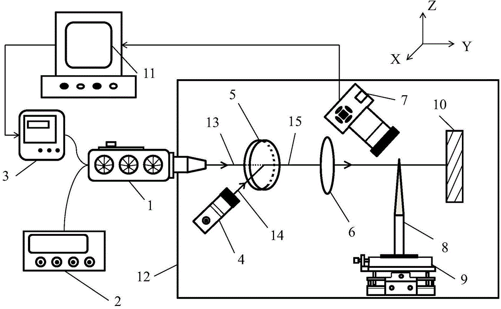
[0028] Such as figure 1 Shown: the present invention relates to a microprobe tip shaping laser processing system, comprising: CO 2 Laser (1), DC power supply (2), power controller (3), laser pointer (4), beam combiner (5), focusing lens (6), microscopic imaging equipment (7), microprobe blank (8), probe position adjustment module (9), laser absorber (10), signal analysis and processing module (11), protective glass cover (12), etc. Described micro-imaging equipment (7) takes CCD micro-imager as example, described microprobe blank (8) takes glass probe as example, and described probe position adjustment module (9) uses precision three-dimensional The displacement platform is taken as an example, and the signal analysis and processing module (11) is described by taking a computer as an example. Concrete process of the present invention can be divided in...


PUM


Abstract

The invention discloses a laser machining system for forming of the pointed end of a microprobe, and relates to the field of machining and manufacturing of the pointed ends of microprobes. The system mainly comprises a laser generation module, an optical path adjustment module, a probe position adjustment module, an on-line monitoring module, a signal analysis and processing module and a laser protection module. Lasers emitted by the laser generation module are gathered at the pointed end of the probe after being adjusted by the optical path adjustment module, and then local rapid heating forming can be performed on the pointed end of the probe; the on-line monitoring module can perform real-time monitoring on the machining process; the signal analysis and processing module controls the whole machining process by adjusting a power controller connected with the signal analysis and processing module. According to the system, the size and position of a heat source acting area can be flexibly adjusted, damage to other areas except for the pointed end of the microprobe is not likely to occur, the system is suitable for performing rapid heating on a micro local area, meanwhile, heating power and heating time can be easily and accurately controlled, and an ideal spherical shape of the pointed end of the microprobe can be obtained within a short time.

Description

technical field [0001] The invention relates to the field of microprobe tip processing and manufacturing, in particular to a microprobe tip shaping laser processing system. Background technique [0002] Microprobes are the core components of measuring instruments such as surface topography measuring instruments, profile measuring instruments, and stylus displacement sensors. They are widely used in industrial production fields such as precision measurement processing and high-end product manufacturing. [0003] For microprobes, a good microsphere tip is essential. How to process the probe so that it has a good microspherical tip is a technical problem to be solved urgently. [0004] The traditional microprobe tip thermoforming processing methods include the following: flame heating forming method, resistance wire heating forming method, arc discharge heating forming method, etc. These processing methods all have their own defects and deficiencies. [0005] The flame firin...

Claims


Application Information

Patent Timeline
Patent Type & Authority Applications(China)
IPC IPC(8): B23K26/00B23K26/70
CPCB23K26/00
Inventor 许斌赵世平唐海容刘乾乾陈伟
Owner SICHUAN UNIV
Why Eureka
Try Eureka