
A monitoring system for a reciprocating compressor

A monitoring system and compressor technology, which is applied in the direction of liquid variable displacement machinery, pump testing, mechanical equipment, etc., can solve the problems of insufficient maintenance, accidents caused by insufficient maintenance, waste of resources and costs, etc., and achieve the effect of ensuring accuracy

Active Publication Date: 2018-03-06
TIANJIN LIANWEI ETHYLENE ENG CO LTD
View PDF6 Cites 0 Cited by
  • Summary
  • Abstract
  • Description
  • Claims
  • Application Information

AI Technical Summary

Problems solved by technology

Among them, the crankshaft rotates under the action of the motor, and the crosshead is the intersection point of the rotary motion and the linear motion to drive the piston and the piston rod to perform linear reciprocating motion. It can be seen that the internal work of the reciprocating compressor is extremely complicated, so in actual production The failure rate of the medium reciprocating compressor is very high, and because of its complex structure and numerous excitation sources, the maintenance process after the failure is also faced with great difficulties. It is inevitable that there will be problems of insufficient maintenance or excessive maintenance, and insufficient maintenance is prone to occur Accidents and excessive maintenance will cause waste of resources and costs. Therefore, it is imperative to develop a "predictive maintenance system" that can monitor the production process in real time for the above problems

Method used


Image

  • A monitoring system for a reciprocating compressor
  • A monitoring system for a reciprocating compressor
  • A monitoring system for a reciprocating compressor

Examples


Embodiment Construction

[0035] The present invention will be described in detail through the following examples, which are illustrative rather than restrictive, and cannot limit the protection scope of the present invention.

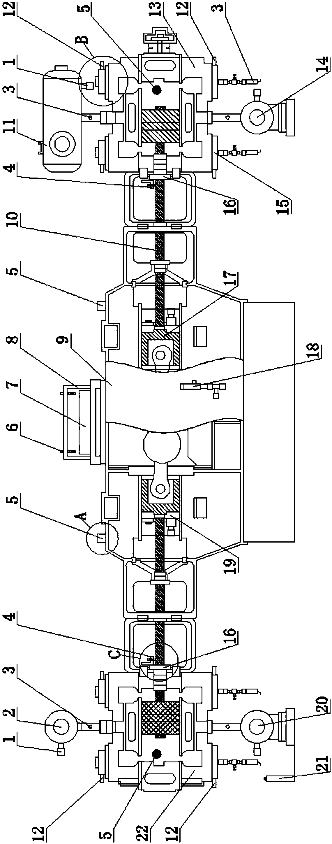
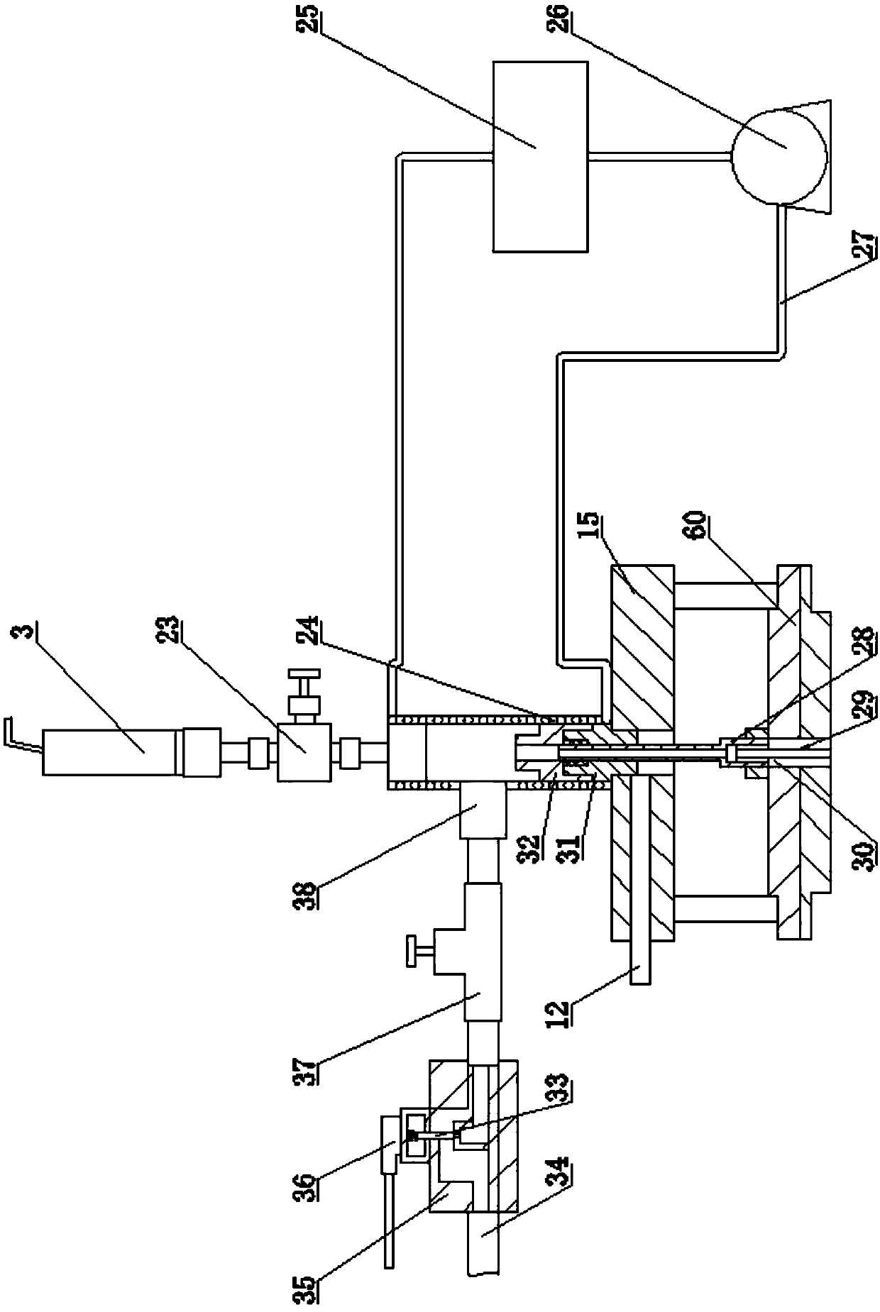
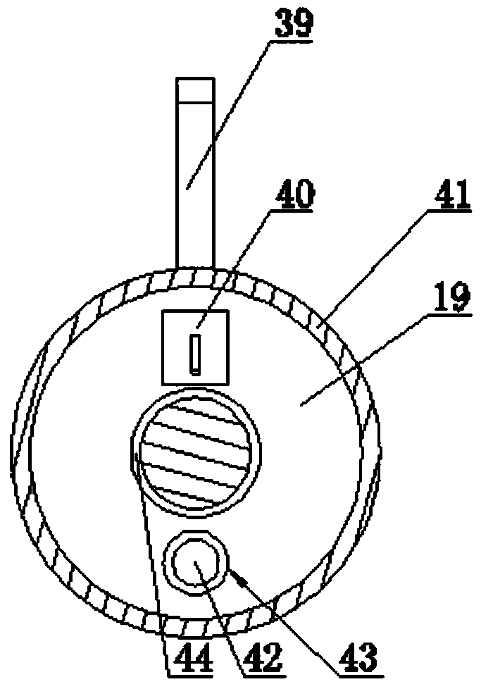
[0036] A monitoring system for a reciprocating compressor, including a reciprocating compressor, the reciprocating compressor includes a body 9, the body is communicated with an overflow valve, the upper end of the body is equipped with a turntable 7, a protective cover 8, the body A section of cylinder 13 and a section of cylinder 22 are respectively installed on both sides, and the section of cylinder is connected and installed with a section of cylinder intake buffer tank 11 and a section of cylinder exhaust buffer tank 14 through a pipeline, and the section of cylinder is connected and installed through a pipeline There are a two-stage cylinder intake buffer tank 2 and a two-stage cylinder exhaust buffer tank 20, and a pressure probe 3 is installed on the outer end surface o...


PUM


Abstract

The invention relates to the field of equipment monitoring, in particular to a monitoring system for a reciprocating compressor. Including a reciprocating compressor, the reciprocating compressor includes a body, the body is connected with an overflow valve, a turntable and a protective cover are installed on the upper end of the body, and a first-stage cylinder and a second-stage cylinder are respectively installed on both sides of the body. The first-stage cylinder and the second-stage cylinder are respectively connected with an intake buffer tank and an exhaust buffer tank, and the two sides of the protective cover installed on the upper end of the body are respectively installed with a key phase displacement sensor at the relative position of the turntable, and the first-stage cylinder and the second-stage cylinder A temperature probe is installed on the outer side of the cylinder head installed on the upper end of the first-stage cylinder, and a temperature probe and a pressure probe are respectively installed in each exhaust valve installed on the lower end of the first-stage cylinder and the second-stage cylinder. A wireless vibration sensor and at least one wireless temperature sensor are respectively installed in one side end faces of the two crossheads connected to the two-stage cylinders respectively.

Description

technical field [0001] The invention relates to the field of equipment monitoring, in particular to a monitoring system for a reciprocating compressor. Background technique [0002] Reciprocating compressors are a type of key power equipment widely used in petroleum, chemical, metallurgy, power and other industrial fields, and play an important role in production like the "heart" of the human body. [0003] The key moving parts of a reciprocating compressor mainly include connecting rods, crankshafts, crossheads, piston rods, and pistons. Among them, the crankshaft rotates under the action of the motor, and the crosshead is the intersection point of the rotary motion and the linear motion to drive the piston and the piston rod to perform linear reciprocating motion. It can be seen that the internal work of the reciprocating compressor is extremely complicated, so in actual production The failure rate of medium reciprocating compressors is very high, and because of its compl...

Claims


Application Information

Patent Timeline
Patent Type & Authority Patents(China)
IPC IPC(8): F04B51/00
Inventor 董玉波王景璐王小杰安宇
Owner TIANJIN LIANWEI ETHYLENE ENG CO LTD
Learn More