Bone screw

A bone screw and screw technology, applied in the direction of internal bone synthesis, medical science, surgery, etc., can solve the problems of inability to stabilize surrounding bones, lack of bone micro-motion, and unfavorable fracture prognosis, and achieve good healing effect, improved surgical success rate, Stabilizing the effect of fixed effects

Active Publication Date: 2015-09-09
HEBEI RUINUO MEDICAL INSTR CO LTD
View PDF9 Cites 10 Cited by
  • Summary
  • Abstract
  • Description
  • Claims
  • Application Information

AI Technical Summary

Problems solved by technology

[0005] The purpose of the present invention is to provide a bone screw to solve the problem that the existing bone screw either has a gap with the surrounding bone and cannot stabilize the surrounding bone immediately after operation, or there is no gap with the surrounding bone and there is always a lack of bone in the early and long term. Minor movement is not conducive to fracture prognosis

Method used


Image

  • Bone screw
  • Bone screw
  • Bone screw

Examples


Embodiment 1

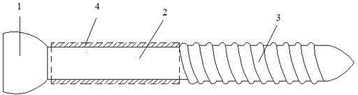
[0031] The bone screw is used as a cancellous bone screw, its diameter is 4.5mm, the major diameter of the screw section 3 (that is, the outer diameter of the thread) is 4.5mm, the diameter of the polished section 2 is 3.2mm, and the length of the polished section 2 is 20mm; Polydioxanone is molded onto the polished rod section 2 of the bone screw by thermal injection to form a degradable material layer 4 . The degradable material layer 4 is closely attached to the peripheral surface of the polished rod section 2, and has a length of 20 mm and a thickness of 0.6 mm. The degradable material layer 4 can also be compounded to the circumferential surface of the polished rod section 2 in other conventional ways.

Embodiment 2

[0033] The bone screw is used as a cancellous bone screw, its diameter is 2.5mm, the major diameter of the screw rod section 3 is 2.5mm, the diameter of the polished rod section 2 is 1.8mm, and the length of the polished rod section 2 is 20mm; Poly-L-lactic acid is molded onto the polished shaft section 2 of the bone screw to form a layer 4 of degradable material. The degradable material layer 4 is closely attached to the peripheral surface of the polished rod section 2, and has a length of 11 mm and a thickness of 0.3 mm.

Embodiment 3

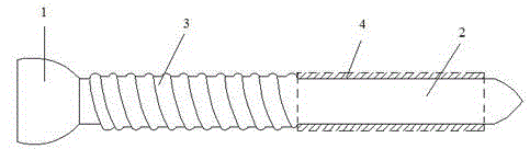
[0035] This bone screw is used as a screw for pressing and locking the steel plate. Its diameter is 4.5mm, the major diameter of the screw rod section 3 is 4.5mm, the diameter of the polished rod section 2 is 3.0mm, and the length of the polished rod section 2 is 40mm. External threads are formed on the outer circle; polydioxanone is molded onto the polished rod section 2 of the bone screw by thermal injection to form a degradable material layer 4 . The degradable material layer 4 is closely attached to the peripheral surface of the polished rod section 2, and has a length of 35 mm and a thickness of 0.7 mm.


PUM

PropertyMeasurementUnit
diameteraaaaaaaaaa
diameteraaaaaaaaaa
lengthaaaaaaaaaa

Abstract

The invention relates to a bone screw. The bone screw comprises a screw pole and a screw cap, the screw pole comprises a polish rod section and a screw rod section, a degradable material layer is compounded on the peripheral circumferential surface of the polish rod section, and the outer diameter of the degradable material layer is less than or equal to the large diameter of the screw rod section. The screw pole and screw cap are made of metal material; the degradable material layer is prepared from one or the polymer of polylactic acid, polyglycolic acid, poly trimethylene carbonate, polydioxanone and poly epsilon-caprolactone. Through operation, the bone screw is stable in fixing effect and avoided from sliding after the fracture part of a patient is fixed and before the degradable material layer is degraded; in the later degradation process of the degradable material layer and after the complete degradation of the degradable material layer, the bone moves slightly to stimulate the full healing of the bone, the achievement ratio of operation is improved, and the healing effect of the fracture part is better.

Description

technical field [0001] The invention relates to an orthopedic surgical instrument, in particular to a bone screw. Background technique [0002] In orthopedic surgery, the traditional approach to fracture management is to place bone screws or bone screw and plate fixation systems directly on the bone to align and stabilize the fracture. Bone screws or nail-plate fixation systems are mostly made of metal materials, and bone screws plus nail-plate rigid connections provide a guarantee for the healing stability of fractures. However, there are problems with this approach. First, when the rigid connection may generate increased stress on the screw-bone interface, the load will be conducted from the bone to the screw and then to the plate, so that the screw or plate absorbs and bears most of the stress. Stress shielding occurs, and after the removal of the plate and screw, bone fracture may occur again. The second is that the rigid structural fixation inhibits the micro-movement...

Claims


Application Information

Patent Timeline
Patent Type & Authority Applications(China)
IPC IPC(8): A61B17/86A61L31/14A61L31/06
CPCA61B17/8625A61B17/8635A61B17/866A61B2017/00831A61L31/06A61L31/14A61L2400/00C08L67/04C08L29/04C08L69/00
Inventor 李开南石春霞
Owner HEBEI RUINUO MEDICAL INSTR CO LTD
Why Eureka
Try Eureka