Single-stroke air pressure engine, implementation method and application of engine

An engine and single-stroke technology, which is applied in the direction of atmospheric engines, engine starting, engine components, etc., can solve problems such as inability to pump air, loss of practicability, and complicated problems

Inactive Publication Date: 2015-09-09
黄锦林 +3
View PDF3 Cites 0 Cited by
  • Summary
  • Abstract
  • Description
  • Claims
  • Application Information

AI Technical Summary

Problems solved by technology

The problem is that according to the design of H1, the crankshaft chamber can only be turned into a vacuum environment, which will cause a series of problems: firstly, the crankshaft itself needs to be lubricated, and the lubricating oil needs to be drained back to the oil pan, unless the oil pan is also vacuum , but the inside of the casing filled with lubricating oil cannot be evacuated. If you first evacuate and then refill the oil, once the air leaks accidentally, it will become impossible to evacuate again, which will complicate the problem and lead to the loss of practicability. For this, in H1 There is no solution; H3 is just the opposite. It creates a vacuum environment on the upper part of the piston, uses external force to do work for the piston, and then uses the pressure difference to complete the second stroke, but the atmospheric pressure acting on the surface of the piston and pulling it back The external force is equal, indicating that the effect of atmospheric pressure pushing the piston is zero, which is meaningless; H2 only has one intake valve, and its working principle is even more incomprehensible, because wh

Method used


Image

  • Single-stroke air pressure engine, implementation method and application of engine
  • Single-stroke air pressure engine, implementation method and application of engine
  • Single-stroke air pressure engine, implementation method and application of engine

Examples


Embodiment Construction

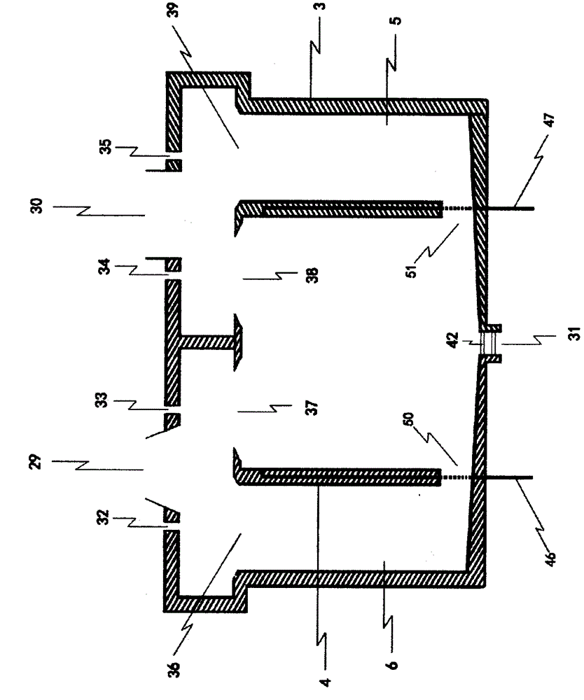
[0081] The following is mainly combined with the accompanying drawings ( Figure 4 ) and attached drawings ( Figure 5 ) The operating principle of the single-stroke pneumatic engine of the present invention is further described. In order to highlight the working principle of the single-stroke pneumatic engine, the description of the structure of the lubrication system will be omitted (for the lubrication scheme, please refer to Figure 8 , Figure 9 , Figure 10 And the description of the aforementioned "structural features of a single-stroke pneumatic engine"). Those skilled in the art should be able to understand that this description omits the lubricating process of the camshaft and other components, including the oil pump and oil pipeline, oil pan, crankcase, engine outer shell and cylinder head, as engine components , although these parts are indispensable in practice, the present invention mainly demonstrates the operating principle of the single-stroke pneumatic en...


PUM


Abstract

The invention provides a brand-new single-stroke air pressure engine technology capable of completely achieving zero oil consumption and zero discharging. The working manner of an engine is changed mainly through changing of a structure or a construction of an engine air cylinder body and a piston, and coordination work of external pressure reduction and pressure increasing equipment and a control system, so that the technology is achieved. A power source of the single-stroke air pressure engine is from atmospheric pressure, and under the common atmospheric environment, without the high-pressure air storage technology and any external force, one single-stroke air pressure engine can be like an internal combustion machine to achieve high-strength long-time uninterrupted efficient work. The dependency of an existing pneumatic engine technology or an existing air pressure engine technology on a high-pressure air storage cylinder and a third party energy or power is avoided, and meanwhile the problem that a traditional engine or power generating equipment uses unclean energy, and consequently, environmental pollution and energy shortage are caused is thoroughly solved.

Description

Technical field: [0001] The invention relates to the fields of pneumatic technology and engine technology. Background technique [0002] Pneumatic engine is a technology that uses air pressure to replace oil and gas as the power source of the engine. It was first developed by the French in the 1990s. Up to now, pneumatic engine vehicles have been commercialized in some countries such as Europe, America and Asia. The attention to technology is late, but it is already in the research and development stage. Some folk enthusiasts have even successfully transformed the internal combustion engine into a pneumatic motor. Theoretically, the application of pneumatic technology can realize zero emission of the engine, and the benefits of protecting the environment are self-evident. However, at present, more mature pneumatic technologies are inseparable from high-pressure gas storage tanks, and the energy conversion rate is low. Due to the constant power consumption and inflation, rea...

Claims


Application Information

Patent Timeline
IPC IPC(8): F01B29/02F01B31/28F01B31/26F01B31/00F01B27/02F01B25/00F01B25/10F01B23/10F01B23/02
CPCF01B29/02F01B23/02F01B23/10F01B25/00F01B25/10F01B27/02F01B31/00F01B31/26F01B31/28
Inventor 黄锦林
Owner 黄锦林
Why Eureka
Try Eureka