Polarization resistance single line polarization interference and single Woodward prism spectral homodyne laser vibrometer

A laser vibrometer and prism spectroscopic technology, used in instruments, measuring devices, measuring ultrasonic/sonic/infrasonic waves, etc., can solve the problems of poor device accuracy, difficult to overcome nonlinear errors, optical path asymmetry, etc., to solve polarization leakage The effect of aliasing with polarization, suppressing polarization leakage and aliasing, and simple optical path

Active Publication Date: 2015-09-09
HARBIN INST OF TECH
View PDF4 Cites 19 Cited by
  • Summary
  • Abstract
  • Description
  • Claims
  • Application Information

AI Technical Summary

Problems solved by technology

The disadvantages of this technical solution are: 1) Placing a polarizer on the reference arm causes the light intensity of the reference light to be greatly reduced relative to the measurement light, and introduces unequal amplitude errors of the two output signals; 2) The interference part is generated by a polarizer Linearly polarized light, the extinction ratio of the polarizer is low, and there is polarization aliasing in the interference part, which introduces nonlinear errors
Its shortcomings are: 1) The accuracy of the one-eighth wave plate device is poor, the actual phase shift is less than 45°, and the linearly polarized reference light passes through the one-eighth wave plate twice to actually obtain elliptically polarized light, resulting in The non-orthogonal phase shift error of the two actually output signals is large; 2) The detection part adopts PBS light splitting, and there is polarization leakage phenomenon, which introduces a large nonlinear error
The disadvantages of this technical solution are: 1) there are many optical elements, and there are many sources of nonlinear errors; 2) the use of polarization beam splitter PBS to split light, there is a phenomenon of polarization leakage, resulting in significant nonlinear errors
The disadvantages of this technical solution are: 1) the detection part requires an additional quarter-wave plate to generate four photoelectric signals with a phase difference of 90°; Equal amplitude and non-orthogonal errors, thus introducing nonlinear errors
The advantage of this technical solution is that the symmetry of the optical path is better, and the non-orthogonal error problem of the solution proposed by Peter is solved. The disadvantages are: 1) The detection part needs an additional quarter-wave plate to generate four Photoelectric signals with a phase difference of 90°; 2) The beam splitter used is an ordinary beam splitter BS, and the beam splitting effect is related to the polarization state of the light incident to the four-channel detection part, and has a large additional phase shift
The disadvantages of this technical solution are: 1) the detection part requires an additional quarter-wave plate to generate four photoelectric signals with a phase difference of 90°; Equal amplitude and non-orthogonal errors, thus introducing nonlinear errors
[0016] In summary, due to factors such as laser power drift, unsatisfactory optical components, and installation errors of optical components, especially the polarization leakage of optical components such as polarizing beam splitters PBS and polarizers, and the phase delay error of wave plate devices, the existing homodyne In the interference part and / or detection part of the orthogonal laser vibrometer technical solution, due to the limitation of the optical path structure, principle and the characteristics of the optical device itself, there are nonlinear errors that are difficult to overcome, and the nonlinear error can reach several nm or even dozens nm, it is difficult to meet real-time, high-precision measurement, especially the vibration measurement requirements of the next generation of sub-nanometer or even picometer-level accuracy, and nano-level amplitude

Method used


Image

  • Polarization resistance single line polarization interference and single Woodward prism spectral homodyne laser vibrometer
  • Polarization resistance single line polarization interference and single Woodward prism spectral homodyne laser vibrometer
  • Polarization resistance single line polarization interference and single Woodward prism spectral homodyne laser vibrometer

Examples


Embodiment Construction

[0029] The specific implementation manner of the present invention will be described in detail below with reference to the accompanying drawings, and examples will be given.

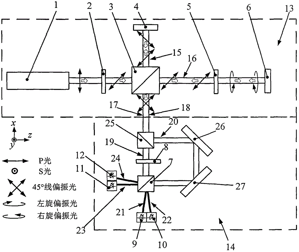
[0030] An anti-polarization aliasing single-line polarization interference and single Wollastedt prism spectroscopic homodyne laser vibrometer is composed of an interference part 13 and a detection part 14, and the interference part 13 is composed of a laser 1, a half The wave plate 2, the first depolarizing beam splitter 3, the measuring mirror 4, the second quarter wave plate 5, and the reference mirror 6 are composed; the laser 1 emits linearly polarized light, which forms a 45° angle after passing through the half wave plate 2 The linearly polarized light is split by the first depolarizing beam splitter 3, the reflected light forms the first beam 15 as the measuring light, and the transmitted light forms the second beam 16 as the reference light; after the first beam 15 is reflected by the measuring m...


PUM


Abstract

Provided is a polarization resistance single line polarization interference and single Woodward prism spectral homodyne laser vibrometer, belonging to the laser interference measuring field. An interference portion utilizes a half-wave plate, a quarter-wave plate and an NBS to generate +/-45 DEG linear polarization reference light and linear polarization measuring light orthorhombic in a one way polarization direction and having light paths overlapped; the reference light and measuring light of a detection portion are split and generate four paths of optoelectronic signals with a phase position difference of 90 DEG through a same Woodward prism, thereby restraining outstanding features of non-linear errors from an optical path structure and principle. The vibrometer realizes four channel homodyne orthogonal laser interference measurement, effectively solves the problems that, in the prior art, polarization leakage and polarization aliasing exist in the optical path, output signals exist direct current biased errors and nonopiate errors, and non-linear errors of measuring results are obvious, and possesses significant technical advantages in an ultra-precision vibration measuring field.

Description

technical field [0001] The invention belongs to the field of laser interferometry, and mainly relates to a single-line polarization interference and single Wollaster prism spectroscopic homodyne laser vibrometer for anti-polarization aliasing. Background technique [0002] As an ultra-precision measuring instrument that can trace the vibration value to the laser wavelength, the laser vibrometer is widely used in the fields of dynamic displacement measurement, vibration measurement and monitoring, ultra-precision equipment and system integration, scientific research and experiments. Laser vibrometers based on laser interferometry can be divided into two categories, homodyne and heterodyne, according to the principle. The two have significant differences in working principle, optical path structure and technical characteristics. The homodyne measurement method uses a single-frequency laser as the light source, based on the classic or improved Michelson laser interference princ...

Claims


Application Information

Patent Timeline
Patent Type & Authority Applications(China)
IPC IPC(8): G01H9/00
Inventor 崔俊宁何张强久元溦姜宏蕾谭久彬
Owner HARBIN INST OF TECH
Why Eureka
Try Eureka