High-gain end-fire millimeter wave antenna

A millimeter-wave antenna, high-gain technology, applied in slot antennas, radiating element structures, circuits, etc., can solve the problems of increasing the complexity of the feeding system, increasing uncertainty, and low gain, etc.

Inactive Publication Date: 2015-09-09
UNIV OF ELECTRONICS SCI & TECH OF CHINA
View PDF4 Cites 18 Cited by
  • Summary
  • Abstract
  • Description
  • Claims
  • Application Information

AI Technical Summary

Problems solved by technology

At present, there are many research reports on millimeter-wave band single antenna (different from array antenna), but there are generally disadvantages such as low gain. Research on high-gain antennas also focuses on the implementation of array antennas. The antenna adopts the array method to increase the feed rate. The complexity of the system adds a lot of uncertainty

Method used


Image

  • High-gain end-fire millimeter wave antenna
  • High-gain end-fire millimeter wave antenna
  • High-gain end-fire millimeter wave antenna

Examples


Embodiment

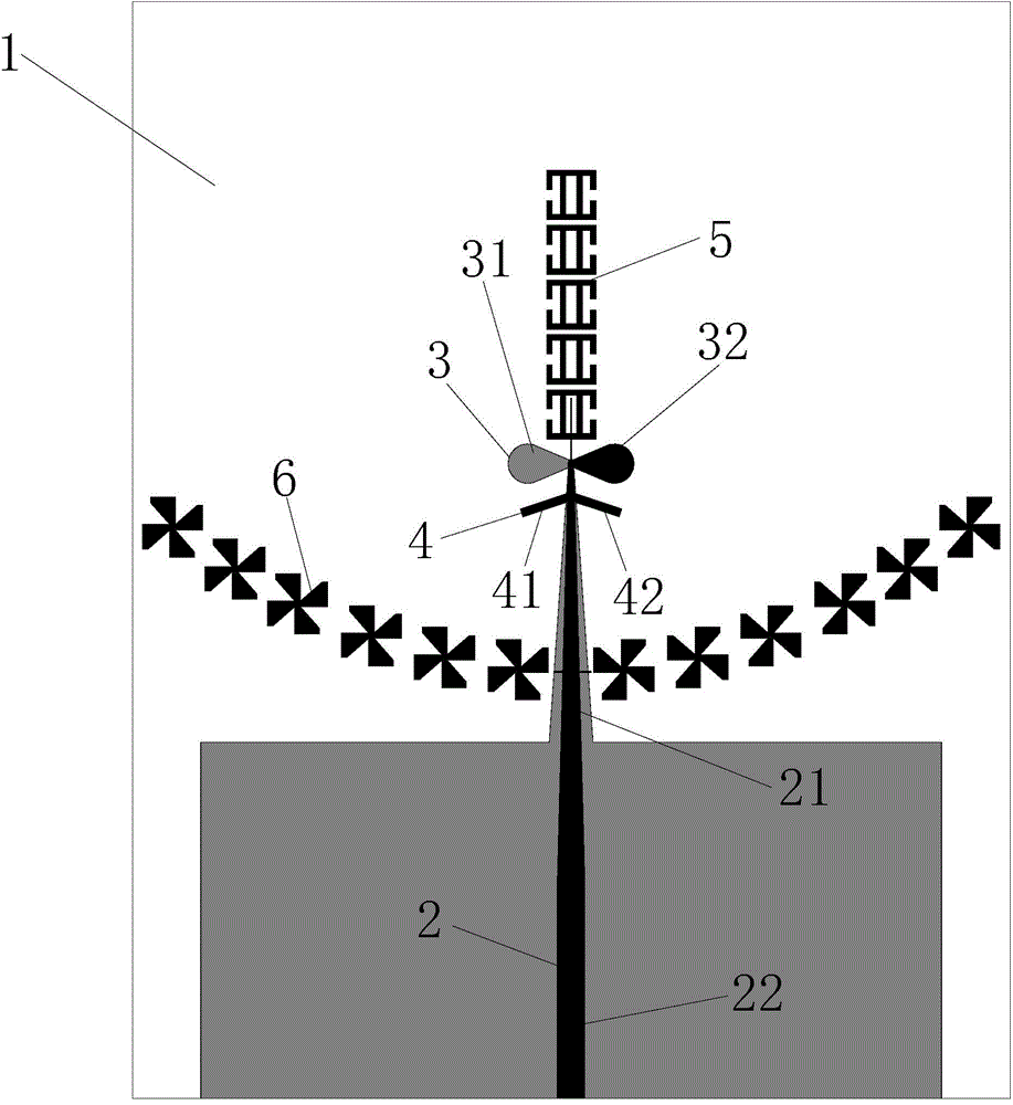
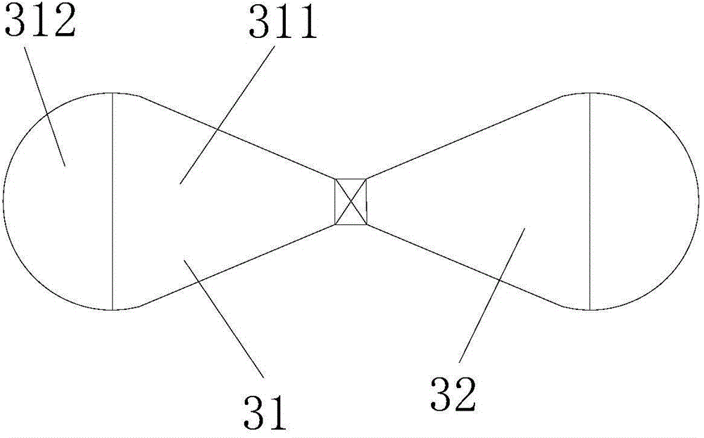
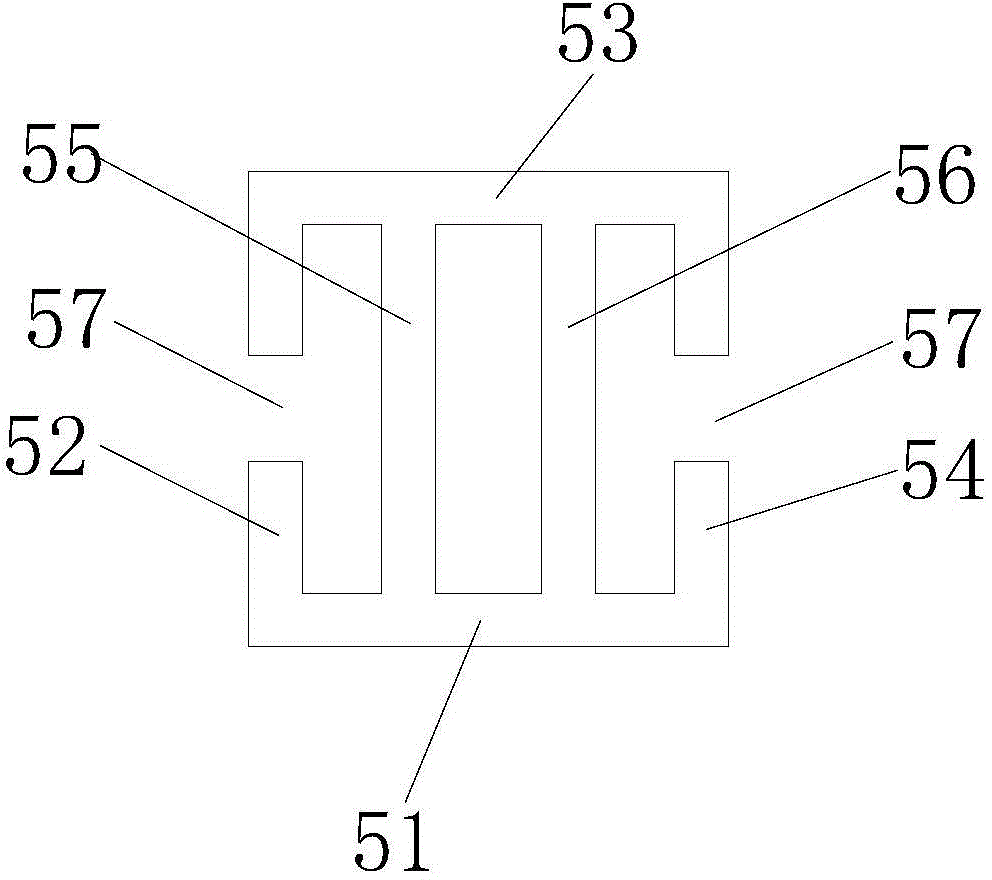
[0034] In this embodiment, the dielectric substrate of the end-fired millimeter-wave antenna is Rogers RO4350, the dielectric constant is 3.66, and the dielectric thickness is 0.254mm. The antenna is fed by a 50Ω microstrip line. The size of the antenna is as follows: Figure 5 to Figure 8 as shown, Figure 5 is a schematic diagram of the geometry of the end-fired millimeter-wave antenna of the present invention; Image 6 It is a schematic diagram of the geometric dimensions of the radiation unit of the end-fired millimeter-wave antenna of the present invention; Figure 7 It is a schematic diagram of the geometric dimensions of the "II" resonant unit of the end-fired millimeter-wave antenna of the present invention; Figure 8 It is a schematic diagram of the geometric dimensions of the reflection unit of the end-fired millimeter-wave antenna of the present invention; the length of the 50-ohm microstrip line E=4mm, W3=0.5mm, D=6.5mm, W2=0.8mm, W7=0.1mm, and the overall dimensi...


PUM


Abstract

The invention discloses a high-gain end-fire millimeter wave antenna. A microstrip wire is adopted by the end-fire millimeter wave antenna and is gradually changed to two feed wires, and feed is provided to a radiation unit for radiation. Multiple reflection units are arranged to be a parabola, so electromagnetic wave reflection is realized, the gain of the antenna is increased, and side lobes are inhibited. The working principle of the antenna is similar to that of a parabolic antenna. A reflection branch is used for compensating the gap of a parabola array formed by the multiple reflection units in the position of the feed wires, thereby inhibiting back lobes and increasing the gain. II resonant units are sequentially arranged on extending lines of the microstrip feed wires and positioned in an end-fire direction, thereby focusing wave beams and increasing the gain. The reflection units, the reflection branch and the II resonant units help to change the radiation directional diagram of a dipolar antenna, so the dipolar antenna which is supposed to enable 8-shaped radiation is changed to enable end-fire radiation. Therefore, the gain of the antenna is increased. The high-gain end-fire millimeter wave antenna is suitable for popularization and applications in the technical field of antennas.

Description

technical field [0001] The invention relates to the technical field of antennas, in particular to a high-gain end-firing millimeter-wave antenna. Background technique [0002] A wireless personal area network (WPAN) is a personal area network that uses a wireless connection. It is used to communicate between mobile phones, computers, accessory devices and digital devices in a small range. Currently, very mature technologies include Bluetooth, WiFi, ZigBee, WiMax, etc. The range covered by WPAN is generally within a radius of 10 meters and must be in the licensed frequency band. It has the characteristics of cheap price, small body, easy operation and low power consumption. [0003] However, in recent years, people's demand for short-distance wireless broadband multimedia high-speed transmission is increasing day by day. Traditional WPAN technology is facing severe challenges, and ultra-high-speed wireless communication technology is urgently needed. In order to solve this ...

Claims


Application Information

Patent Timeline
Patent Type & Authority Applications(China)
IPC IPC(8): H01Q1/38H01Q13/10H01Q1/36
Inventor 高鹏王宁
Owner UNIV OF ELECTRONICS SCI & TECH OF CHINA
Why Eureka
Try Eureka