Cloud type dust removal system

A technology of dust removal system and dust removal device, which is applied in the direction of dispersed particle separation, chemical instruments and methods, and the use of liquid separation agents, etc., which can solve the problem of corrosion of fan blades and tail flue, affecting the dilution and diffusion of pollutants, and the large drop in flue gas temperature and other problems, to achieve low cost, good separation effect, and reduce the effect of fluid drag

Active Publication Date: 2015-09-16
苏州云式环境科技有限公司
View PDF7 Cites 14 Cited by
  • Summary
  • Abstract
  • Description
  • Claims
  • Application Information

AI Technical Summary

Problems solved by technology

[0005] However, some common problems are gradually exposed in the actual operation of the currently used wet dust collectors: ① The exhausted flue gas is heavily water-laden, which will not only cause dust to stick to the impeller of the induced draft fan, produce abnormal vibration, but also cause serious corrosion Fan blades and tail flue; ②The exhausted flue gas temperature drops too much, which will reduce the lift height of the flue gas discharged from the chimney, which will affect the dilution and diffusion of pollutants

Method used


Image

  • Cloud type dust removal system
  • Cloud type dust removal system
  • Cloud type dust removal system

Examples


Embodiment 1

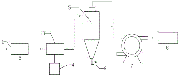
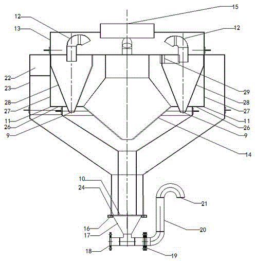
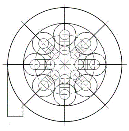
[0038] Embodiment 1, with reference to figure 1 , a cloud-type dust removal system, the front end of the device is a feed inlet 1, and the feed inlet 1 is sequentially connected with a cloud generator or an atomization box 2, a particle growth area or an expansion joint 3, a cloud-type collection area or a cloud-type dust removal The device 5, the induced draft fan 7, and the outlet concentration measurement area 8 are sealed and connected; the bottom of the particle growth area or expansion joint 3 is connected to the sewage tank 4; the bottom of the cloud collection area or cloud dust removal device 5 is connected to the ash discharge device 6 and the particle growth area or expansion joint The outlet of section 3 is tangentially connected to the upper end of the cloud-type collection area or the cloud-type dust collector device. Wherein, the cloud type collection area or cloud type dedusting device 5 (refer to figure 2 , image 3 ) is mainly composed of a central cylind...

Embodiment 2

[0042] Example 2, the cloud generator or atomization box 2 and the particle growth area or expansion joint 3 are not in accordance with each other figure 1 The sequence shown is connected, but the cloud generator or atomization box 2 is installed on the side of the particle growth area or expansion joint 3, the feed port 1 is directly connected to the particle growth area or expansion joint 3, and the cloud generator or atomization box 2 The generated mist is sucked in under negative pressure from the particle growth area or the side of the expansion joint 3, and the dust-laden airflow and the mist are directly in contact with the particle growth area or the expansion joint 3. The rest are the same as embodiment 1.

Embodiment 3

[0043] Embodiment 3, the cloud generator or the atomization box 2 can be installed in the particle growth area or the expansion joint 3 so that the two are integrated. The rest are the same as embodiment 1.


PUM

PropertyMeasurementUnit
Particle sizeaaaaaaaaaa

Abstract

The invention relates to a cloud type dust removal system. The cloud type dust removal system is characterized in that a feeding hole is arranged at the most front end of the cloud type dust removal system and is sequentially communicated with a cloud-mist generator or an atomization box, a particle growing region or an expansion joint, a cloud type collection region or a cloud type dust removal device, a draught fan and an outlet concentration determination region in a sealing manner; a dirt discharge groove is communicated to the bottom of the particle growing region or the expansion joint; an ash discharge device is communicated to the bottom of the cloud type collection region or the cloud type dust removal device, and an outlet of the particle growing region or the expansion joint is in tangential communication with the cloud type collection region or the cloud type dust removal device. According to the cloud type dust removal system, the dust removal rate can reach 99.6%-99.9%, and the capture rate of fine particulate matter (PM2.5) reaches 95%.

Description

technical field [0001] The invention relates to a dust removal system, in particular to a cloud-type dust removal system which utilizes cloud principles to capture dust, especially fine particles (PM2.5). Background technique [0002] Air pollution is one of the important factors affecting our country's environment, among which dust pollution is an important part of air pollution. Studies have shown that fine particulate matter (PM2.5) in dust is easy to enrich heavy metals, acid oxides, organic pollutants, bacteria and viruses in the air, and its harm to human health is much higher than that of coarse particulate matter. Therefore, it is of great significance to control dust pollution, especially the emission of fine particles. (Zhang Danian, Research on Inhalable Particulate Matter in Urban Atmosphere, [J] Shanghai Environmental Science, 1999, 18(4): 154-157) [0003] At present, the commonly used dust removal systems in industry include cyclone dust collector, electrost...

Claims


Application Information

Patent Timeline
IPC IPC(8): B01D47/06
Inventor 王博
Owner 苏州云式环境科技有限公司
Why Eureka
Try Eureka