Synchronous movement realization based free-piston compressor

A technology of synchronous motion and compressors, applied in the field of compressors, can solve the problems of small bearing capacity, unbalanced inertial force, large stroke control error, etc., and achieve the effect of large bearing capacity

Active Publication Date: 2015-09-16
MIANYANG POWER SUPPLY COMPANY STATE GRID SICHUANELECTRIC POWER +1
View PDF6 Cites 5 Cited by
  • Summary
  • Abstract
  • Description
  • Claims
  • Application Information

AI Technical Summary

Problems solved by technology

[0003] The purpose of the present invention is to overcome the complicated structure of the above-mentioned existing compressor, low mechanical efficiency, unequal mass of the piston groups, unbalanced inertia force when the machine is running, need to configure a heavy foundation, and the bearing capacity is small, and the stroke control error is large To solve the problem, a free-piston compressor based on synchronous motion is designed. The mass of the moving piston groups of the free-piston compressor can be completely equal, and the inertial force of the machine is completely balanced when the machine is running. There is no need to configure a heavy foundation. Large bearing capacity, precise control of the stroke, solves the complex structure of the existing compressor, low mechanical efficiency, unequal mass of the piston group, unbalanced inertia force when the machine is running, needs to be equipped with a heavy foundation, and the bearing capacity is small, The problem of large stroke control error

Method used


Image

  • Synchronous movement realization based free-piston compressor

Examples


Embodiment 1

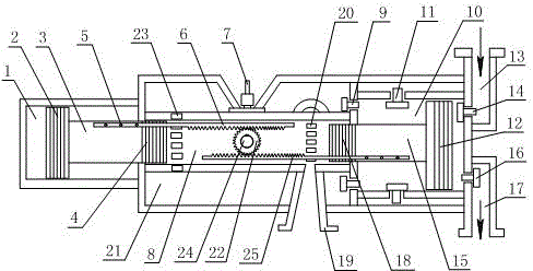
[0013] Such as figure 1 As shown, based on the free piston compressor realizing synchronous movement, it includes a hollow and sealed air storage box 21. The symmetrical ends of the air storage box 21 are respectively connected with the buffer cylinder 1 and the compressor cylinder 10. The air storage box 21 A power cylinder 8 is arranged in the middle, and the two ends of the power cylinder 8 respectively pass through the air storage tank 21 and are arranged in the corresponding buffer cylinder 1 and compressor cylinder 10. Two power pistons are arranged in the power cylinder 8, and the outer wall of the power piston They are all in seamless contact with the inner wall of the power cylinder 8, and the ends of the power pistons far away from each other are connected with piston rods, one of which is connected with a buffer piston 2, and the buffer piston 2 is arranged in the buffer cylinder 1 and connected to the inner wall of the buffer cylinder 1 Seamless contact, the other ...


PUM


Abstract

The invention discloses a synchronous movement realization based free-piston compressor. A gas storage tank is connected with a cushion cylinder and a compressor cylinder, a power cylinder is arranged in the gas storage tank and arranged in the cushion cylinder and the compression cylinder, power pistons are arranged in the power cylinder and connected with piston rods, the piston rods are connected with a cushioning piston and a compressor piston, the cushioning piston is arranged in the cushion cylinder, and the compressor piston is arranged in the compressor cylinder. The compressor cylinder is provided with a first suction valve and a first exhaust valve, the power is provided with a gear, a gear shaft is arranged in the gear and fixed to the power cylinder, and racks are arranged on the gear, meshed with the gear and fixed to the piston rods correspondingly. The power cylinder is provided with suction holes and exhaust holes. The free-piston compressor can make moving piston sets completely equal in mass, inertia force during operation of a machine is fully balanced, bearing capacity is large, and accurate control in stroke is realized.

Description

technical field [0001] The invention relates to a compressor, in particular to a free piston compressor based on synchronous motion. Background technique [0002] Compressor, a driven fluid machine that lifts low-pressure gas into high-pressure gas. It is the heart of the refrigeration system. It inhales low-temperature and low-pressure refrigerant gas from the suction pipe, drives the piston to compress it through the operation of the motor, and discharges high-temperature and high-pressure refrigerant gas to the exhaust pipe to provide power for the refrigeration cycle, thereby realizing Compression → condensation (heat release) → expansion → evaporation (heat absorption) refrigeration cycle. Compressors are divided into piston compressors, screw compressors, centrifugal compressors, etc. Piston compressors generally consist of a housing, motor, cylinder, piston, control equipment (starter and thermal protector) and cooling system. There are two cooling methods: oil coo...

Claims


Application Information

Patent Timeline
Patent Type & Authority Applications(China)
IPC IPC(8): F04B31/00
Inventor 李招银
Owner MIANYANG POWER SUPPLY COMPANY STATE GRID SICHUANELECTRIC POWER
Why Eureka
Try Eureka