
Axial cooling radial coil type parallel magnetic circuit electromagnet

A cooled, electromagnet technology applied to electromagnets. It can solve the problems of reducing the safety and reliability of the coil, reducing the dynamic response speed of the electromagnet, weakening the eddy current, etc., to achieve the effects of improving the control accuracy and diesel engine economy, improving the rising speed and decay speed, and good magnetic permeability.

Active Publication Date: 2015-09-16
HARBIN ENG UNIV
View PDF7 Cites 6 Cited by
  • Summary
  • Abstract
  • Description
  • Claims
  • Application Information

AI Technical Summary

Problems solved by technology

Whether it is electronically controlled pump nozzles, unit pumps, distribution pumps, or the fastest-growing high-pressure common rail electronically controlled fuel injection system, high-speed electromagnets are the most critical and core components to ensure their normal operation. , the electronically controlled fuel injection system of diesel engine realizes the precise control of cycle fuel injection volume, fuel injection timing and fuel injection law through the precise control of high-speed electromagnet movement by the electronic control unit, but its use still has the following disadvantages: for high-speed work For diesel engines, the electromagnet is magnetized repeatedly at high frequency. Due to the magnetic permeability of the electromagnet material itself, the hysteresis and eddy current loss will inevitably increase, resulting in an increase in heat production. At the same time, in order to meet the high response requirements of the electromagnet, a large Current driving to speed up its response speed increases the calorific value of the coil, resulting in an increase in the operating temperature of the electromagnet, and the increase in the operating temperature of the electromagnet will reduce the magnetic permeability of the magnetic material and the dynamic response speed of the electromagnet. At the same time, the resistance of the coil wire increases and the conductivity decreases, resulting in an increase in output power and a decrease in the safety and reliability of the coil; in addition, there is a contradictory relationship between the lift of the armature of the electromagnet and its response, that is, increasing the lift of the armature will cause the response speed of the electromagnet to increase. Slow down, it is difficult to meet the requirements of solenoid response and control valve flow at the same time
The electromagnet core adopts the combination form of silicon steel sheet and soft magnetic integral material, which weakens the eddy current to a certain extent and can reduce the temperature of the electromagnet core, but it is still a traditional E-shaped structure, only the upper end surface of the iron core It can be in contact with the cooling liquid for efficient convection heat exchange, while the middle part of the iron core and the coil mainly exchange heat through heat conduction, and the thermal resistance is large, and the heat transfer efficiency is low, so the coil and the middle part of the iron core cannot be well cooled, resulting in The temperature of the coil and core cannot be effectively reduced

Method used


Image

  • Axial cooling radial coil type parallel magnetic circuit electromagnet
  • Axial cooling radial coil type parallel magnetic circuit electromagnet
  • Axial cooling radial coil type parallel magnetic circuit electromagnet

Examples


Embodiment Construction

[0033] The present invention is described in more detail below in conjunction with accompanying drawing example:

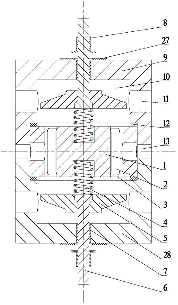
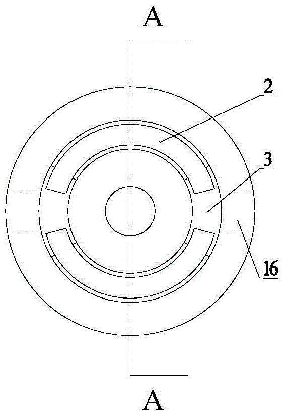
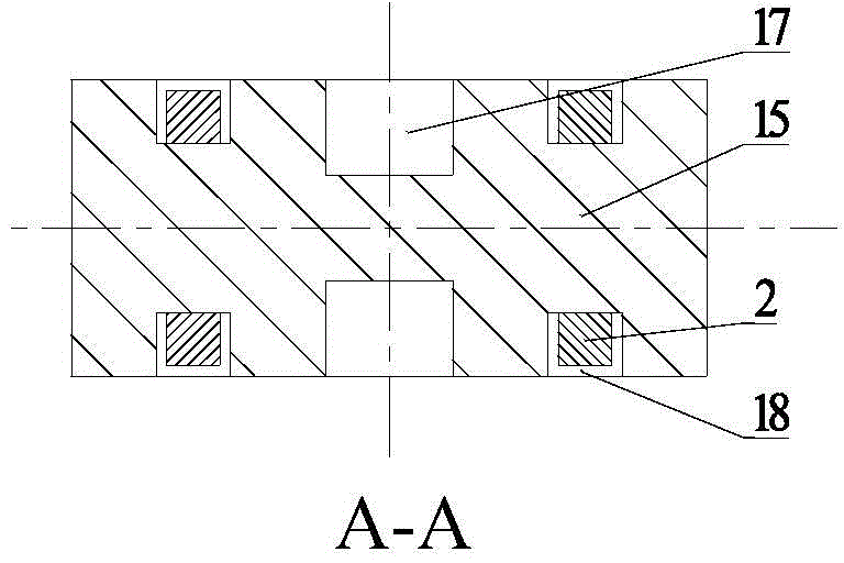
[0034] combine Figure 1-13 , The composition of the first embodiment of the axially cooled radial coil type parallel magnetic circuit electromagnet of the present invention includes an axially cooled iron core 1, a radial coil 2, an armature return spring 4, an armature 5, and a valve stem 6 , Valve sleeve 7, stop ring 8, rubber buffer gasket 27, upper housing 9, lower housing 28 and residual air gap adjustment ring 12. The upper shell 9 is square, with four bolt through holes 20 on the end face, and the center is provided with an iron core hole 19 and an armature chamber 10 in turn. There is a valve sleeve hole 21, which is embedded with a valve sleeve 7. In addition, the side of the upper housing 9 is provided with an armature chamber coolant inlet 11. The valve stem 6 is fixedly connected with the armature 5, and passes through the valve sleeve 7 of the upper...


PUM


Abstract

The goal of the invention is to provide an axial cooling radial coil type parallel magnetic circuit electromagnet. The electromagnet comprises an axial cooling type iron core, a radial type coil, an armature reset spring, armatures, a valve rod, a valve pocket, a stop ring, a rubber buffer washer, an upper shell, a lower shell and a residual air gap adjusting ring. The axial cooling radial coil type parallel magnetic circuit electromagnet of the invention could effectively cool the inner side of the iron core and the coil, reduce surface hydraulic pressure of the armature, damping force acted on the armature, inductance of the coil by performing distributed arrangement to a traditional single multi-turn coil, improve rising velocity and decay rate of the current in the coil, and quicken the response speed of the electromagnet. In addition, by using the principle of a parallel magnetic circuit, the axial cooling radial coil type parallel magnetic circuit electromagnet of the invention shares the axial cooling type iron core and the radial type coil to synchronously control the two armatures and act on same control chamber so as to increase flow of a control valve while ensuring the response speed so that the pressure in the control chamber could be discharged fast and the fuel cut of a fuel injector is straightforward. The axial cooling radial coil type parallel magnetic circuit electromagnet of the invention is conductive to improving control precision of oil injection and economical efficiency of a diesel engine, thereby reducing emission.

Description

technical field [0001] The invention relates to an electric control device for fuel injection of a diesel engine, specifically an electromagnet. Background technique [0002] Due to its characteristics of high injection pressure, fuel injection timing and fuel injection regularity flexible and controllable, the electronically controlled fuel injection system of diesel engine is an effective means to improve the high fuel economy of diesel engine and reduce the emission of harmful substances, and has been widely used. Whether it is electronically controlled pump nozzles, unit pumps, distribution pumps, or the fastest-growing high-pressure common rail electronically controlled fuel injection system, high-speed electromagnets are the most critical and core components to ensure their normal operation. , the electronically controlled fuel injection system of diesel engine realizes the precise control of cycle fuel injection volume, fuel injection timing and fuel injection law thr...

Claims


Application Information

Patent Timeline
Patent Type & Authority Applications(China)
IPC IPC(8): H01F7/08F02M51/06
Inventor 范立云刘鹏赵建辉周伟马修真宋恩哲姚崇
Owner HARBIN ENG UNIV
Learn More