Fuel-gas-catalyzing flameless near-infrared direct heating porous medium combustor

A technology of porous media and gas catalysis, applied to gas fuel burners, burners, combustion methods, etc., can solve the problems of uneven distribution of heating temperature, uneven distribution of premixed gas, high emission of combustion pollutants, and achieve surface temperature Stable, less exhaust, high heating efficiency

Inactive Publication Date: 2015-09-23
周海波
View PDF7 Cites 6 Cited by
  • Summary
  • Abstract
  • Description
  • Claims
  • Application Information

AI Technical Summary

Problems solved by technology

[0002] At present, the combustion of gaseous fuels in my country's industrial production is mainly space combustion characterized by free flames. The temperature gradient near the flame surface of this combustion method is steep and the temperature distribution is uneven. The existence of local high-temperature areas causes a large amount of NO X At the same time, there are still problems such as incomplete combustion, low thermal efficiency, poor combustion stability, and high emissions of combustion pollutants. The patent with the authorized public number CN101929676B discloses a catalytic porous media burner. It can effectively reduce the emission of combustion pollutants, but because the premixed gas directly enters the catalytic metal fiber felt and ceramic foam from the premixed chamber through the porous plate for combustion, the distribution of the premixed gas is still not uniform enough, so that the heating temperature distribution is not uniform enough. Its heating efficiency is still low

Method used


Image

  • Fuel-gas-catalyzing flameless near-infrared direct heating porous medium combustor
  • Fuel-gas-catalyzing flameless near-infrared direct heating porous medium combustor

Examples


Embodiment 1

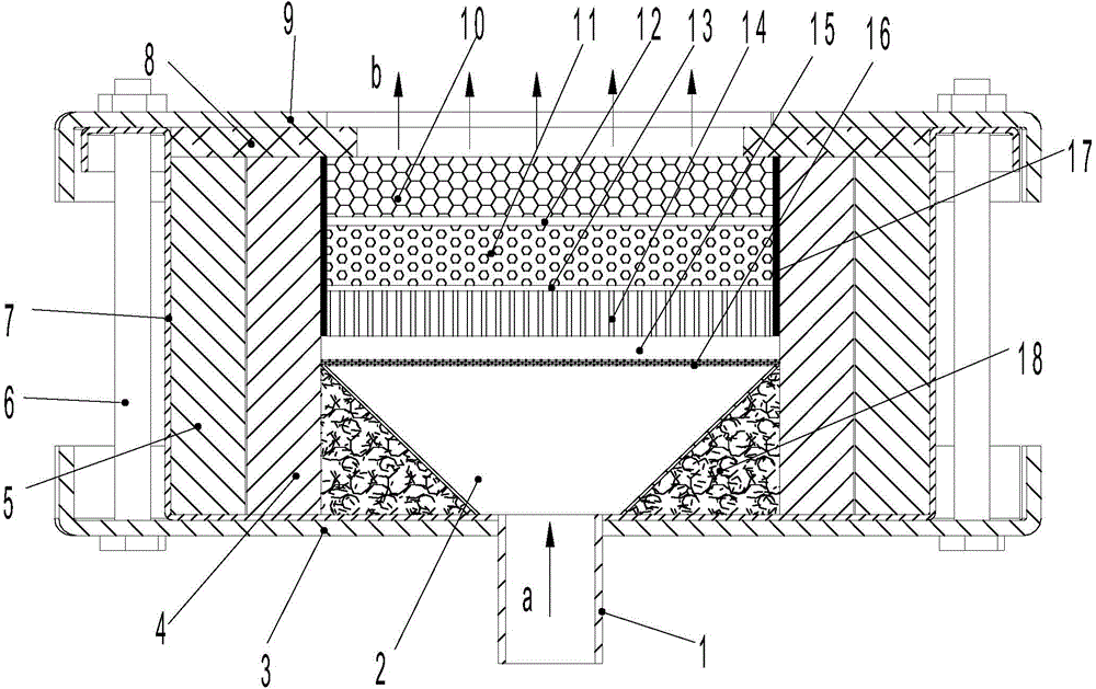
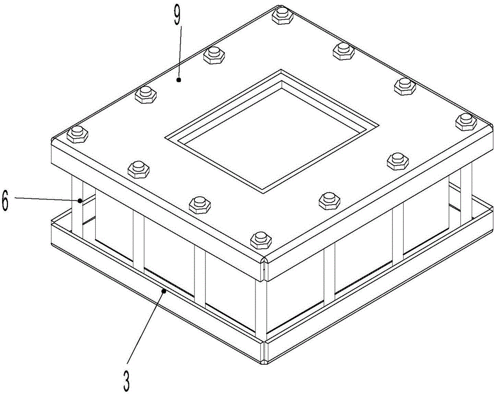
[0048] A gas catalytic flameless near-infrared direct heating porous media burner (see figure 1), including a burner body 7, an insulating layer 5, and a refractory brick layer 4. The refractory brick layer 4 is located in the burner body 7, and the insulating layer 5 is located between the refractory brick layer 4 and the burner body 7. The described The refractory brick layer 4 is sequentially provided with a premixed gas diffusion chamber 2, a perforated plate 16, a premixed gas pressure equalization chamber 15, a flame-resistant barrier plate 14, and a foam ceramic plate from the bottom to the top. The premixed gas diffusion chamber 2 The bottom of the premixed gas supply pipe 1 is in communication with the premixed gas diffusion chamber 2, and insulation cotton 18 is arranged between the periphery of the premixed gas diffusion chamber 2 and the refractory brick layer 4. Together; the upper end surface of the burner body 7 is also provided with an upper compression plate 9...

Embodiment 2

[0060] A gas catalytic flameless near-infrared direct heating porous media burner, the basic structure of the burner is the same as that of Embodiment 1, the difference is that the porosity of the macroporous ceramic foam plate 10 is 90%, and the pore diameter is 20PPI, the plate thickness is 50mm; the porosity of the small-hole foam ceramic plate 11 is 90%, the pore diameter is 65PPI, and the plate thickness is 50mm; holes, the hole spacing is 20mm; the plate thickness of the perforated plate 16 is 4mm, and the holes with a diameter of 3mm are evenly arranged on the perforated plate 16, and the hole spacing is 20mm; the plate thickness of the upper pressing plate 9 and the burner body 7 are 8mm.

Embodiment 3

[0062] A gas catalytic flameless near-infrared direct heating porous media burner, the basic structure of the burner is the same as that of Embodiment 1, the difference is that the porosity of the macroporous ceramic foam plate 10 is 85%, and the pore diameter is 15PPI, the plate thickness is 30mm; the porosity of the small-hole foam ceramic plate 11 is 85%, the pore diameter is 60PPI, and the plate thickness is 20mm; mm holes, the hole spacing is 10mm; the plate thickness of the perforated plate 16 is 2mm, and the holes with a diameter of 2mm are evenly arranged on the perforated plate 16, and the hole spacing is 10mm; the plate thickness of the upper pressing plate 9 and the burner body 7 are uniform is 5mm.

[0063] As a transformation of the above-mentioned embodiments 1 to 3, the porosity of the macroporous ceramic foam plate 10 is 80-90%, the pore diameter is 10-20PPI, and the plate thickness is 10-50mm; the pores of the small-porous ceramic foam plate 11 The rate is 80...


PUM

PropertyMeasurementUnit
thicknessaaaaaaaaaa
thicknessaaaaaaaaaa
thicknessaaaaaaaaaa

Abstract

The invention provides a fuel-gas-catalyzing flameless near-infrared direct heating porous medium combustor, and relates to a combustor. The combustor comprises a combustor body, a heat preservation layer and a fireproof brick layer. A premixed gas diffusion chamber, a perforated plate, a premixed gas pressure equalizing chamber, a flame retardant shield plate and a foam ceramic plate are sequentially arranged in the fireproof brick layer from bottom to top. The bottom of the premixed gas diffusion chamber is communicated with a premixed gas supply pipe. Heat preservation cotton is arranged between the periphery of the premixed gas diffusion chamber and the fireproof brick layer. The flame retardant shield plate is bonded to the foam ceramic plate through a bonding plate A. The upper end face and the lower end face of the combustor body are provided with an upper pressing plate and a lower pressing plate respectively. The upper pressing plate and the lower pressing plate are pressed and connected together through fastening pieces. By means of the fuel-gas-catalyzing flameless near-infrared direct heating porous medium combustor, smoke and flame are not generated in combustion, heating efficiency is high, even heating is achieved, emission of NOX can be lowered, the surface temperature is stable in combustion, radiation intensity is high, tempering can be prevented, and the combustor has the advantages of being convenient to mount, long in service life, wide in application range, capable of saving energy, environmentally friendly and the like and easy to apply and popularize.

Description

technical field [0001] The invention relates to a burner, in particular to a gas catalytic flameless near-infrared direct heating porous medium burner. Background technique [0002] At present, the combustion of gaseous fuels in my country's industrial production is mainly space combustion characterized by free flames. The temperature gradient near the flame surface of this combustion method is steep and the temperature distribution is uneven. The existence of local high-temperature areas causes a large amount of NO X At the same time, there are still problems such as incomplete combustion, low thermal efficiency, poor combustion stability, and high emissions of combustion pollutants. The patent with the authorized public number CN101929676B discloses a catalytic porous media burner. It can effectively reduce the emission of combustion pollutants, but because the premixed gas directly enters the catalytic metal fiber felt and ceramic foam from the premixed chamber through th...

Claims


Application Information

Patent Timeline
Patent Type & Authority Applications(China)
IPC IPC(8): F23D14/18F23D14/02F23D14/46
CPCF23D14/18F23D14/02F23D14/46F23D2203/105
Inventor 周海波
Owner 周海波
Why Eureka
Try Eureka