
Micronano metal fiber surface topography measuring device, use method thereof and movement distance measuring method of drive in device

A metal fiber and surface topography technology, applied in measurement devices, instruments, scanning probe microscopy, etc., can solve the problems of insufficient identification of surface atoms, complex sample preparation technology, limited sample research objects, etc. Economic and social benefits, wide measurement range, and the effect of broadening use cases

Active Publication Date: 2015-09-23
YANGZHOU UNIV
View PDF5 Cites 5 Cited by
  • Summary
  • Abstract
  • Description
  • Claims
  • Application Information

AI Technical Summary

Problems solved by technology

These techniques play an important role in the research of various fields of surface science, but any technique has limitations in one way or another in its application, for example, diffraction methods such as low-energy electron diffraction and X-ray diffraction require samples to be periodic. Structure, the resolution of optical microscope and scanning electron microscope is not enough to distinguish surface atoms, high-resolution transmission electron microscope is mainly used for bulk phase and interface research of thin layer samples, field electron microscope and field ion microscope can only detect The atomic structure and two-dimensional geometric properties on the tip of the needle, and the sample preparation technology is complex, which can be used as a sample research object is very limited; there are also some surface analysis techniques, such as X-ray photoelectron spectroscopy, ultraviolet photoelectron spectroscopy and energy loss spectroscopy can only provide spatially averaged electronic structure information
In addition, some of the above analysis techniques also have special requirements for the measurement environment, such as vacuum conditions, etc.

Method used


Image

  • Micronano metal fiber surface topography measuring device, use method thereof and movement distance measuring method of drive in device

Examples


Embodiment Construction

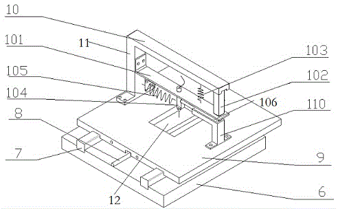
[0035] 1. A measuring device for micro-nano metal fiber surface topography, comprising base 6, base 9, beam 10, side beam 101, electrode 104 and guide rail 7 and template 8 fixed on the base, the side beam is flexible copper made of sheet material.

[0036] The base is installed on the base through guide rails, and the base is provided with a telescopic device 110, that is, a driver 106, and the guide rails can control the base to move along the X direction. On one side of the base facing the base, there is a chute for template movement in the middle, the chute is parallel to the guide rail, the template is placed in the chute, and the center of the base is provided with a viewing window 12 for observing the template.

[0037] The beam is placed directly above the side beam, one end of the beam is connected to the base through the support leg 11, one end of the side beam is connected to the support leg, the other end is placed on the top of the driver, and a driver 102 is provid...


PUM

PropertyMeasurementUnit
Diameteraaaaaaaaaa
Widthaaaaaaaaaa

Abstract

The invention discloses a micronano metal fiber surface topography measuring device, a use method thereof and a movement distance measuring method of a drive in the device. A substrate is arranged on a base through a rail. A chute is arranged in the middle of the base. A template is placed in the chute. A visual window is arranged at the center of the base. One end of a cross beam is connected with the base. One end of a side beam is connected with a support leg, and the drive is arranged on the other end. One end of an electrode is arranged on the side beam. The other end points to the surface of the template through the visual window. The distance from one end, which points to the template, of the electrode to the surface of the template is 0.01 to 100nm. According to the invention, a produced tunnel current effect is used to scan the surface of a measured object, and the three-dimensional shape of the surface of the measured object is acquired through difference in current magnitude.

Description

technical field [0001] The invention relates to a device for measuring the surface topography of micro-nano metal fibers, a method for using the same, and a method for measuring the moving distance of a driver in the device. Background technique [0002] Nano science and technology (Nano-ST) is a new technology that was just born in the late 1980s and is on the rise. Manipulate and arrange atoms and molecules to create new substances. Nanotechnology is one of the important contents of the scientific and technological industrial revolution in the 21st century. It is a highly interdisciplinary and comprehensive subject, involving relevant knowledge of multiple disciplines such as physics, chemistry, biology, materials science and electronics. It not only includes basic disciplines with observation, analysis and research as the main line, but also technical science with nano-engineering and micro-mechanics as the main line. Therefore, nano-science and technology is also a comp...

Claims


Application Information

Patent Timeline
IPC IPC(8): G01Q60/14G01Q10/00
Inventor 边义祥夏咸龙
Owner YANGZHOU UNIV
Learn More