Capacitor-carried power supply ground plane modeling and capacitor decoupling radius simulating method
A technology of power supply ground plane and capacitor power supply, which is applied in the electronic field, can solve the problem that the resonator cannot model the ground plane of the load power supply, and achieve the effect of ensuring calculation accuracy and improving calculation efficiency
- Summary
- Abstract
- Description
- Claims
- Application Information
AI Technical Summary
Problems solved by technology
Method used
Image
Examples
Embodiment 1
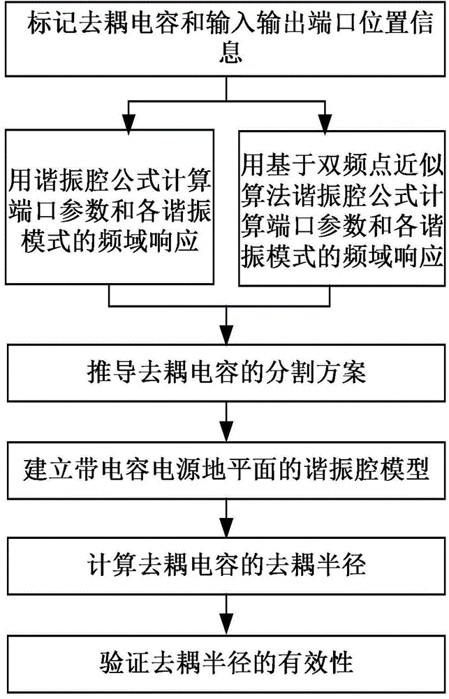
[0035] Embodiment 1: the present invention is a kind of ground plane modeling and capacitive decoupling radius emulation method with capacitive power supply, see figure 1 , including the following steps:
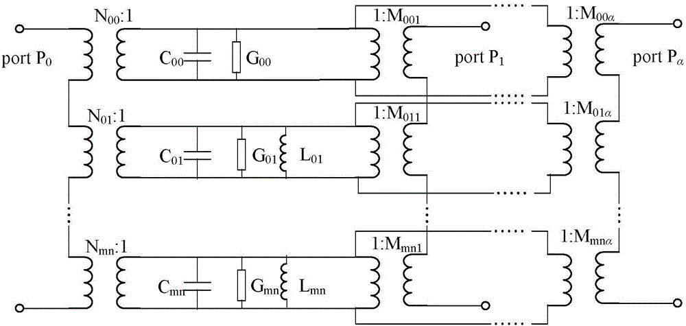
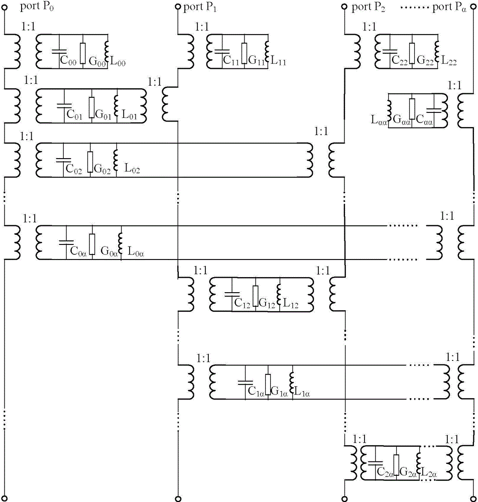
[0036] (1) Use the port P for the position of the input / output port on the power ground plane 0 marked, the location of the decoupling capacitor on the power ground plane is marked with port P 1 , P 2 ,...,P α mark, where α is the number of decoupling capacitors terminated on the power ground plane, and record the coordinates of the decoupling capacitors and the positions of the input / output ports respectively, see Figure 2(a), image 3 , Figure 4 , Figure 13(a).
[0037] (2) The coordinates of the decoupling capacitor k=1,2,…,α, coordinates of input / output ports The length a of the power supply ground plane, the width b and the interval d between the power supply plane and the ground plane are substituted into the resonant cavity formula, and the frequency domain ...
Embodiment 2
[0045] Embodiment 2: ground plane modeling with capacitance power supply and capacitance decoupling radius simulation method, with embodiment 1, refer to Figure 5 , calculating the effective decoupling radius of the decoupling capacitor in step (5) includes the following steps:
[0046] 5.1) Calculate the frequency-domain impedance distribution of the power ground plane after adding decoupling capacitors by using the closed resonant cavity formula with a capacitive power ground plane;
[0047] 5.2) According to the performance requirements of the actual circuit, set the target impedance. Since the circuit structure in this example does not involve specific circuit design, set the target impedance to 1Ω;
[0048] 5.3) Scan the frequency-domain impedance distribution of the entire power ground plane in the circuit board, and mark the area where the impedance amplitude is smaller than the target impedance as an effective decoupling area, see Figure 5 , the area with impedance ...
Embodiment 3
[0050] Embodiment 3: ground plane modeling with capacitance power supply and the emulation method of capacitance decoupling radius are the same as embodiment 1-2, wherein in step (2), on the basis of power ground plane resonator formula, calculate the value of each resonant mode of power ground plane Frequency domain response and port coefficients for each port. Any two ports P on the power ground plane i and P j The resonant cavity formula between is shown in the following formula:
[0051] Z P i P j ( ω ) = Σ n = 0 ∞ Σ m = 0 ∞ N mnP ...
PUM
| Property | Measurement | Unit |
|---|---|---|
| Capacitance | aaaaa | aaaaa |
Abstract
Description
Claims
Application Information
 - R&D
- Intellectual Property
- Life Sciences
- Materials
- Tech Scout
- Unparalleled Data Quality
- Higher Quality Content
- 60% Fewer Hallucinations
Browse by: Latest US Patents, China's latest patents, Technical Efficacy Thesaurus, Application Domain, Technology Topic, Popular Technical Reports.
© 2025 PatSnap. All rights reserved.Legal|Privacy policy|Modern Slavery Act Transparency Statement|Sitemap|About US| Contact US: help@patsnap.com


